
Related Manuals for Rae VRAE PGM-7800


Summary of Contents for Rae VRAE PGM-7800
- Page 1 VRAE MULTI GAS MONITOR PGM-7800 & 7840 OPERATION AND MAINTENANCE MANUAL (Document No.: 017-4001) Rev. E RAE SYSTEMS INC. 1339 Moffett Park Drive Sunnyvale, CA 94089 July 2001...
- Page 2 How can I be informed and updated? Be sure t o mail in your warranty card, email or fax us to get on RAE’s private database (information is never supplied to others). You will be updated on new products, technical advisory notices, new...
-
Page 3: Table Of Contents
Table of Contents 1. GENERAL INFORMATION........... 1-1 General Specifications................. 1-2 2 OPERATION OF VRAE........... 2-1 Physical Description ................2-2 Keys and Display ................2-4 Power On/Off..................2-7 Operations ..................2-10 Alarm Signals ..................2-18 Back Light................... 2-21 Preset Alarm Limits and Calibration..........2-22 Integrated Sampling Pump ............... - Page 4 4.7.4 Change Real Time Clock............4-32 4.7.5 Change Back Light Mode............ 4-33 4.7.6 Change Password ..............4-34 4.7.7 Change Pump Speed............. 4-35 4.7.8 Change Averaging Method ..........4-36 4.7.9 Change Temperature Unit............ 4-37 Change Sensor Configuration ............4-38 4.8.1 Change LEL/VOL Sensor Type........... 4-40 4.8.2 Enable/Disable Sensor............
- Page 5 Troubleshooting Table ............... 8-9 APPENDIX A. QUICK REFERENCE GUIDE...........A-1 APPENDIX B. RESPONSE INFORMATION ..........B-1 APPENDIX C. V-RAE DATA CONVERSION TO MICROSOFT ® EXCEL ..................C-1 APPENDIX D. RAE SYSTEMS TECHNICAL NOTES.........D-1 APPENDIX E. RAE SYSTEMS APPLICATION NOTES ……..E-1 APPENDIX F. LITERATURE REQUEST FORM……………...…...F-1 APPENDIX G.
- Page 6 ! WARNING ! - DO NOT proceed before reading - This manual must be carefully read by all individuals who have or will have the responsibility for using, maintaining, or servicing this product. The product will perform as designed only if it is used, maintained, serviced accordance...
- Page 7 Special Notes When the PGM-7800 or PGM-7840 Multi gas monitor is taken out from the transport case and turned on for the first time, there may be some residual organic or inorganic vapor trapped inside the detector chamber. The initial toxic sensor reading may indicate a few ppm. Ensure an area free of toxic vapor and turn on the monitor.
- Page 8 WARNINGS: Use only RAE Systems battery packs, part Nos. 012- 3050, 012-3051 or 012-3052. This instrument has not been tested in an explosive gas/air atmosphere having an oxygen concentration greater than 21%. Substitution of components may impair intrinsic safety. Recharge batteries only in non-hazardous locations.
- Page 9 CALIBRATION WARNINGS: The calibration of all newly purchased RAE Systems instruments should be tested by exposing the sensor(s) to known concentration calibration gas(es) before putting the unit into service for the first time.
- Page 10 AVERTISSEMENT: La calibration de toute instruments de RAE Systems doivent être testé en exposant l’instrument a une concentration de gaz connue par une procédure dietalonnage avant de mettre en service l’instrument pour la première fois. Pour une securite maximale, la sensibilité du VRAE doit être verifi er en exposant l’instrument a une...
-
Page 11: General Information
GENERAL INFORMATION 1 GENERAL INFORMATION The VRAE is a programmable multi gas monitor designed to provide continuous exposure monitoring of toxic gases, oxygen and combustible gases for workers in hazardous environments. Two models of VRAE are available: PGM- 7800 and PGM-7840. The PGM-7840 has one more inorganic toxic sensor in lieu of an oxygen sensor in the PGM-7800. -
Page 12: General Specifications
GENERAL INFORMATION 1.1 General Specifications Table 1.1 VRAE Gas Monitor Specification Dimensions: 7.75”L x 2.75”W x 1.5”H (19.6 cm x 7.0 cm x 3.8 cm) Weight: 19 oz (540 g) with battery. Detector: 5 sensors: electrochemical sensors for toxic gases, oxygen sensor, catalytic bead combustible gases thermal... - Page 13 GENERAL INFORMATION Multi Gas Monitor Specification (Continued) Alarm Settings: Separate alarm limit settings for TWA, STEL, Low and High alarm. Range, Resolution and Response Time (t diffusion): 0-500 ppm 1 ppm 40 sec 0-100 ppm 1 ppm 35 sec 0-20 ppm 0.1 ppm 35 sec 0-250 ppm 1 ppm...
- Page 14 GENERAL INFORMATION Multi Gas Monitor Specification (Continued) Intrinsic Safety: UL & cUL Class 1, Division I, Group A, B, C, D (US & Canada), EEx ia IIC T2 (Europe). No effect when exposed to 0.43mW /cm 2 EM Immunity: RF interference (5 watt transmitter at 12 inches).
-
Page 15: Operation Of Vrae
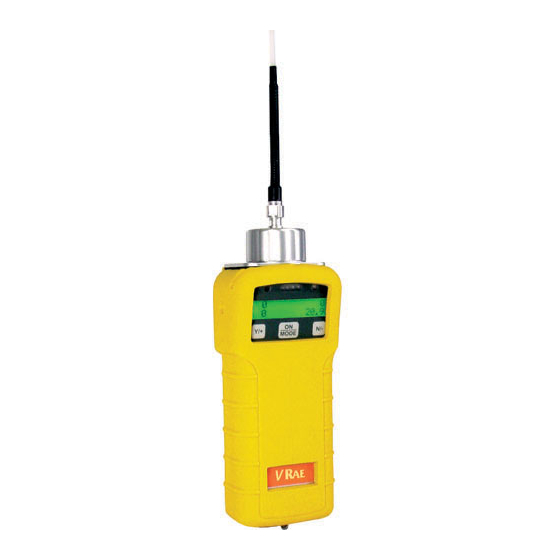
OPERATION OF VRAE 2 OPERATION OF VRAE The VRAE Monitor is a walkie-talkie size multi-gas exposure monitor. It gives real time measurements and activates alarm signals whenever the exposure exceeds preset limits. Prior to factory shipment, the VRAE is preset with default alarm limits and the sensors are pre-calibrated with standard calibration gas. -
Page 16: Physical Description
OPERATION OF VRAE 2.1 Physical Description Figure 2.1 shows the main components of the VRAE Multi gas monitor which include: LED alarm LCD Display Keys Gas Inlet Serial port Gas Outlet Wrist strap Charge contact Figure 2.1 Major parts of the VRAE Multi Gas Monitor •... - Page 17 OPERATION OF VRAE • Charge contact for plugging directly to the charging station. • Gas entry and exit port. • Serial communication port for PC interface. • Analog output and external alarm output port. 2 - 3...
-
Page 18: Keys And Display
OPERATION OF VRAE 2.2 Keys and Display Figure 2.2 shows the LCD display and the keypad on the front panel of the monitor. The functions of the 3 keys during normal operation are summarized in Table 2.1 on the next page: Alarm LED Light Sensor Charging LED... - Page 19 OPERATION OF VRAE Table 2.1 Function in Normal Operation [MODE]: Turn on/off the power* and choose different display mode. Toggle on/off the backlight. [N/-]: [Y/+]: Alarm test and alarm acknowledge (turn off latched alarm, turn on pump or LEL sensor). * Pressing and holding [MODE] key for 5 seconds turns off...
- Page 20 OPERATION OF VRAE • Peak and minimum gas concentrations for toxic, oxygen (not applicable PGM-7840) combustible gases. • 8-hour Time Weighted Average (TWA) or running average and 15 minute Short Term Exposure Limit (STEL) values of the toxic gases in ppm. •...
-
Page 21: Power On/Off
OPERATION OF VRAE 2.3 Power On/Off To turn on the VRAE multi gas monitor, press the [MODE] key. The audio buzzer will beep once and the display will show “ON!..” and then “MultiGas Monitor Ver n.nn” to indicate the software version number. Serial number, current date and time, temperature of the monitor are displayed next. - Page 22 OPERATION OF VRAE Turning off the multi gas monitor with the AC adapter in place will result in a display of “Charging..” or “Battery Charged” and indication of battery voltage. This indicates that the monitor is off, but the smart charger circuit is now active.
- Page 23 OPERATION OF VRAE For instructions and operations of datalog features, please refer to Sections 4.6 and 5 of this manual. 2 - 9...
-
Page 24: Operations
OPERATION OF VRAE 2.4 Operations The VRAE multi gas monitor offers three different user modes of operation: Text mode, Display mode, and Program mode. The text mode is the simplest mode of operation. The monitor will display the sensor name after the monitor is turned on. - Page 25 OPERATION OF VRAE LEL gas names, to show pump speed, and to print reading (Option) and to communicate with a PC. In the program mode, the user can perform all of the functions of the display mode. In addition, the user can enter a Programming Mode.
- Page 26 OPERATION OF VRAE The followings are the brief explanations of each LCD display in the text mode or the display mode operation for the model PGM-7800. For the model PGM-7840, the displays will be similar. However, the oxygen reading will be replaced by a toxic sensor reading, and the name “oxy”...
- Page 27 OPERATION OF VRAE PEAK 20.9 4) The Minimum reading is the lowest reading of each gas concentration since the monitor was turned on. The reading is updated at one-second intervals and is shown in the LCD display with “MIN” message. 19.9 5) The STEL reading is the last 15-minute average reading of the gas concentration.
- Page 28 OPERATION OF VRAE The user can also choose to display “running average”, instead of the TWA. See Section 4 for details on how to select running average or TWA. When running average is selected, the LCD display will show “AVG”, instead of “TWA”.
- Page 29 OPERATION OF VRAE the LCD display together with the current date, time and temperature. 8/3/96 8:30 On = 3:50 20°C 9) The datalog menu shows the current datalog mode. If the VRAE monitor is non-datalog monitor, this menu will not show up. If manual datalog mode is selected, the menu will prompt the user to turn on or off datalogging.
- Page 30 OPERATION OF VRAE 13) If the serial printer option is enabled through the Pro- RAE suites, a new menu item is shown “Print Reading?” Connect a Rae specified serial printer to the serial port of the monitor. By pressing the “Y” key, the current instantaneous readings of the monitor will be printed out from the serial printer.
- Page 31 OPERATION OF VRAE Display time out In all displays, the LCD will automatically return to the instantaneous reading (in display or program mode) or sensor name (in text mode) after a one-minute timeout interval if no key is pressed. 2 - 17...
-
Page 32: Alarm Signals
OPERATION OF VRAE 2.5 Alarm Signals The built-in microcomputer constantly updates and monitors gas concentration and compares it with the programmed alarm limits (TWA, STEL, and two instantaneous alarm limits: Low & High). Whenever the concentration exceeds any of the preset limits, the loud buzzer and red flashing LED are activated immediately to warn the user of the alarm condition. - Page 33 OPERATION OF VRAE It is possible to setup the VRAE from a PC or in programming mode so that when an alarm condition occurs, the alarm signals stay on even after the alarm condition is no longer present. This is called the “latching alarm” mode. The alternative mode is to automatically reset the alarm signal when the alarm condition is cleared.
- Page 34 OPERATION OF VRAE Pump failure 2 beeps/flash per second plus “Pump” message on LCD LEL sensor off 3 beeps/flash per second plus LEL sensor name and “Off” message on LCD Low battery 1 flash per second, 1 beep per minute plus “Bat” message on Memory full 1 flash per second plus “Mem”...
-
Page 35: Back Light
OPERATION OF VRAE 2.6 Back Light The LCD display is equipped with an LED back light to assist in reading the display under poor lighting conditions. In manual mode, this back light can be turned on manually by pressing and holding the [N/-] key for one second in normal operation. -
Page 36: Preset Alarm Limits And Calibration
OPERATION OF VRAE 2.7 Preset Alarm Limits and Calibration The VRAE Multi gas monitor is factory calibrated with standard calibration gas, and is programmed with default alarm limits as listed below. Refer to Section 4 for programming procedures if new calibrations or alarm limits are required. -
Page 37: Integrated Sampling Pump
OPERATION OF VRAE 2.8 Integrated Sampling Pump The VRAE multi gas monitor includes an integrated sampling pump. This is a diaphragm pump providing 400 cc per minute flow rate at the high setting. Connecting a 1/4 inch Tygon tubing with 1/8 inch inside diameter to the gas inlet port of the VRAE, this pump can pull in air samples from 200 feet away horizontally, or 90 feet vertically (see Technical Note 140 for tubing volumes and delay times). -
Page 38: Datalogging
OPERATION OF VRAE 2.9 Datalogging This function is not applicable to non-datalog monitor. The VRAE Multi gas monitor calculates and stores the gas readings based on user-specified datalogging period and the type of measurement. Two types of gas measurements, average or peak concentration, can be stored for each sensor during each datalogging interval. - Page 39 OPERATION OF VRAE Start/stop datalogging manually If manual datalogging mode has been selected from the normal operation menu, toggle through the menu using the key until the “Start Datalog?” prompt is [MODE] displayed. Pressing the [Y/+] key turns on datalogging. key while “Stop Datalog?”...
- Page 40 OPERATION OF VRAE Datalogging event Each time a datalogging operation is initiated, a datalog event is created. Information, such as start time, datalogging period, alarm limits, etc. will be recorded in the event header, followed by the measurement data. Datalogging pause Under the following conditions, the datalogging will be paused automatically: 1) When entering programming mode, datalogging will...
-
Page 41: Operation Of Accessories
OPERATION OF ACCESSORIES 3 OPERATION OF ACCESSORIES The accessories for VRAE include: • Battery Charger • Alkaline Battery Adapter • Water Trap Filter 3 - 1... -
Page 42: Battery Charging Operation
OPERATION OF ACCESSORIES 3.1 Battery Charging Operation The charging circuit of the VRAE is built into the monitor. It only needs a regular AC to 12V DC adapter (wall mount transformer) to charge the monitor. 1. Connect the AC adapter (or the optional automotive charging adapter) to the DC jack on the VRAE monitor. - Page 43 OPERATION OF ACCESSORIES NOTE: If a Ni-Cd battery is used, perform occasional deep discharge to the battery to maintain full capacity. The deep discharge cycle can be done proceeding a charge cycle by powering the unit with the AC adapter. The display will prompt: Deep Discharge? Press the [Y/+] key.
- Page 44 OPERATION OF ACCESSORIES WARNING: To reduce the risk of ignition of hazardous atmospheres, recharge battery only in area known to be non-hazardous. Remove and replace battery only in area known to be non- hazardous. Ne charger les batteries que dans emplacements designes non-dangereux.
-
Page 45: Alkaline Battery Adapter
The internal charging circuit will automatically detect the alkaline battery adapter and prevent charging of the battery. Note: The AA Alkaline battery adapter supplied by RAE Systems Inc. is intrinsically safe! 3 - 5... -
Page 46: Water Trap Filter
OPERATION OF ACCESSORIES 3.3 Water Trap Filter ® The water trap filter is made of PTFE (Teflon ) membrane with a 0.2 micron pore size to prevent water from being sucked into the sensor manifold, which would cause extensive damage to the monitor. It will also remove any dust and other particles from entering the monitor and prolong the operating life of the sensor. -
Page 47: Programming Of Vrae
PROGRAMMING OF VRAE 4 PROGRAMMING OF VRAE The VRAE Monitor is built with a microcomputer to provide programming flexibility for the user. Authorized users can re-calibrate the monitor, change the alarm limits, change site ID, user ID, datalogging period, real time clock, etc. Programming is menu-driven to provide intuitive end-user operation. -
Page 48: Programming Mode
PROGRAMMING OF VRAE 4.1 Programming Mode text, display and The VRAE has three user modes: program mode. The user can access the programming mode menu only if they are in the program mode (or from text mode with password). If the monitor is set to display mode, the user cannot enter the programming mode. - Page 49 PROGRAMMING OF VRAE Security Level There are three levels of security in the VRAE programming mode to provide further protection against unauthorized changes to the monitor alarm settings and other settings. The level 2 security allows a user to enter programming mode without any restriction.
-
Page 50: Keys For Programming Mode
PROGRAMMING OF VRAE 4.2 Keys for Programming Mode The three keys perform a different set of functions during the programming mode as summarized below. Table 4.2 Function in Programming Menu [MODE]: Exit menu when press momentarily or exit data entry mode when pressed and held for 1 second Increase alphanumerical value for data [Y/+]:... -
Page 51: Entering Into Programming Menu
PROGRAMMING OF VRAE 4.3 Entering into Programming Menu 1. Turn on the VRAE monitor (refer to Section 2.3 for the power on sequence). 2. Press and hold down both [MODE] [N/-] keys for three seconds to enter programming mode. Note: this is to prevent the user from entering the programming mode by accident. - Page 52 PROGRAMMING OF VRAE 6. If the correct digit value is not “0”, use [Y/+] key or [N/-] key to increase or decrease the digit value. Then press key momentarily to confirm the digit value. [MODE] Display shows the actual digit entered and moves the flashing cursor to the next digit (to the right).
-
Page 53: Calibration Of Vrae Monitor
PROGRAMMING OF VRAE 4.4 Calibration of VRAE Monitor CALIBRATION WARNINGS: The calibration of all newly purchased RAE Systems instruments should be tested by exposing the sensor(s) to known concentration calibration gas before the instrument is put into service the first time. -
Page 54: Fresh Air Calibration
PROGRAMMING OF VRAE 4.4.1 Fresh Air Calibration This procedure determines the zero point of the sensor calibration curve. To perform fresh air calibration, the calibration adapter and a bottle of “fresh” air (optional) are recommended. The “fresh” air is clean dry air with 20.9% oxygen concentration and without any organic, toxic or combustible gases or impurities. - Page 55 PROGRAMMING OF VRAE 1. “Calibrate Monitor?” is the first menu item in Table 4.1. Press [Y/+] to perform calibration. The first sub-menu shows: “Fresh Air Calibration?” 2. If the “fresh” air bottle is available, snap in the calibration adapter over the inlet port of the VRAE Monitor and connect the other end of the tube to the fresh gas bottle, as shown in Fig.
-
Page 56: Multiple Sensor Calibration
PROGRAMMING OF VRAE 4.4.2 Multiple Sensor Calibration This function simultaneously determines the second point of calibration curves for multiple sensors in the monitor. A bottle of mixed standard reference gases is needed to perform this procedure. The user can choose several gas mixtures* to be used in multiple-sensor calibration. - Page 57 PROGRAMMING OF VRAE seconds while the monitor performs calibration. When the countdown timer reaches 0, the display shows the name of each sensor, the message “cal’ed!” and the calibrated value for each gas. If no gas has reached the sensor after 60 seconds, the display will show “ No gas flow…”...
- Page 58 PROGRAMMING OF VRAE Press the [Y/+] key to select the sensor and the [N/-] key to de-select the sensor. A previously selected sensor will show an “*” next to the sensor name. A previously de-selected sensor will not show an “*” next to the sensor name.
-
Page 59: Single Sensor Calibration
PROGRAMMING OF VRAE 4.4.3 Single Sensor Calibration This procedure determines the second point of the sensor calibration curve for a single sensor. A bottle of standard reference gas (span gas) is needed to perform this procedure. Table 2.2 shows the standard calibration gases typically used as span gases in the factory. - Page 60 PROGRAMMING OF VRAE cal’ed reading = 50 ppm If no gas has reached the sensor after 60 seconds, the display will show “No gas flow…” and abort the calibration. Note: The reading should be very close to the span gas value.
- Page 61 PROGRAMMING OF VRAE Oxygen Sensor Calibration (Not applicable to PGM-7840) The oxygen sensor calibration is slightly different from all other sensors. The oxygen sensor measures a range from 0 to 30% of oxygen in the air. During “fresh” air calibration, the oxygen sensor is calibrated to fixed 20.9% of oxygen.
-
Page 62: Modify Span Gas Value
PROGRAMMING OF VRAE 4.4.4 Modify Span Gas Value This function allows the user to change the span values of the standard calibration gases. The lower left position may toggle betwe en different values when switching between LEL(or Autorange) or VOL% modes. 1. -
Page 63: Change Lel Span Gas
PROGRAMMING OF VRAE 4.4.5 Change LEL/VOL Span Gas This function allows the user to select a specific LEL and/or VOL gas to be used as the span gas during LEL/VOL gas calibration. The LEL and VOL gases must be the same. For the LEL mode, setting this gas lets the unit apply the proper correction factor when calibrating to methane. - Page 64 PROGRAMMING OF VRAE 5. The display shows “Save?” To confirm the new gas selection, press the [Y/+] key to accept the change. Press key or the key to discard the change [N/-] [MODE] and return to the first display. 4 - 18...
-
Page 65: Change Alarm Limits
PROGRAMMING OF VRAE Change Alarm Limits In the programming mode, the users may change alarm limits VRAE of each sensor for the Monitor. Table 4.4 shows the sub-menus for changing the alarm limits. Table 4.4 Alarm Limit Sub-Menu Change High Alarm limit? Change Low Alarm limit? Change STEL alarm limit? Change Average alarm limit? - Page 66 PROGRAMMING OF VRAE 50.0 19.5 25.0 STEL 10.0 10.0 2. To modify this limit, starting from the left-most digit, use the [Y/+] [N/-] key to change the digit value and press the [MODE] key momentarily to advance to the next digit. The flashing digit will move on to the next digit to its right.
-
Page 67: View Or Change Datalog
PROGRAMMING OF VRAE 4.6 View or Change Datalog VRAE monitor calculates and stores the gas readings at a specified interval. The user can review these stored readings or change datalog setup from the programming mode. Users can also program additional datalog options in a PC and download them to the monitor (see Section 5.0 for details on how to program additional datalogging options). -
Page 68: Reset Peak And Minimum
PROGRAMMING OF VRAE 4.6.1 Reset Peak and Minimum This function will reset peak and minimum data stored in the data memory. 1. “Reset Peak and Minimum?” is the first sub-menu item in Table 4.5. 2. Press the [Y/+] key to clear the peak and minimum data memory. -
Page 69: Clear All Data
PROGRAMMING OF VRAE 4.6.2 Clear All Data This function will erase all data stored in the non-volatile data memory. This does not change STEL, TWA, Peak, minimum concentration and run time values which are stored in the regular data memory. 1. -
Page 70: Change Datalog Period
PROGRAMMING OF VRAE 4.6.3 Change Datalog Period The datalog period can be programmed from 1 to 3,600 seconds (1 hour). 1. “Change Datalog Period?” is the third sub-menu item in Table 4.5. 2. Press the [Y/+] key, the display shows “New Period = 0060”... -
Page 71: Select Data Type
PROGRAMMING OF VRAE 4.6.4 Select Data Type The user can choose to store either the average or the peak value during each datalog period. 1. “Select Data Type?” is the fourth sub-menu item in Table 4.5. 2. Press the [Y/+] key, the display shows the current data type, for example, “Data Type = Average?”... -
Page 72: View Datalog
PROGRAMMING OF VRAE 4.6.5 View Datalog This function allows the user to review all the data that is stored in the non-volatile data memory. 1. “View Datalog?” is the fifth sub-menu item in Table 4.5. Press the [Y/+] key and the LCD display shows the first event number and start date and time of the event. -
Page 73: Enable/Disable Datalog
PROGRAMMING OF VRAE 4.6.6 Enable / Disable Datalog The user can choose to enable or disable the datalogging function on each individual sensor. This allows users to selectively log certain sensor readings of interest. 1. “Enable / Disable Datalog?” is the sixth sub-menu item in Table 4.5. -
Page 74: Change Monitor Setup
PROGRAMMING OF VRAE 4.7 Change Monitor Setup In the programming mode, the users may change monitor setup or enter user information for the VRAE monitor. Table 4.6 shows the sub-menus for changing the monitor. Table 4.6 Monitor Setup Sub-Menu Change Site ID? Change User ID? Change Alarm Mode? Change User Mode? -
Page 75: Change Site Id & Change User Id
PROGRAMMING OF VRAE 4.7.1 Change Site ID & Change User ID The user can enter an 8 digit alphanumeric site ID & User ID in the programming mode. These ID’s will be included in the datalog report. 1. “Change Site ID?” and “Change User ID?” are the first and second sub-menu items in Table 4.6. -
Page 76: Change Alarm Mode
PROGRAMMING OF VRAE 4.7.2 Change Alarm Mode There are two different alarm modes: Latched and Automatic Reset in VRAE that can be selected from the programming menu. 1. “Change Alarm Mode?” is the third sub-menu item in Table 4.6. 2. Press the [Y/+] key, the display shows the current alarm mode selection: “Alarm Mode = Latched?”... -
Page 77: Change User Mode
PROGRAMMING OF VRAE 4.7.3 Change User Mode There are three different user modes: text, display, and program in VRAE that can be selected from the programming menu. 1. “Change User Mode?” is the fourth sub-menu item in Table 4.6. 2. Press the [Y/+] key, the display shows the current user mode selection: “User Mode = Program?”... -
Page 78: Change Real Time Clock
PROGRAMMING OF VRAE 4.7.4 Change Real Time Clock The VRAE monitor is equipped with a real time clock. The user can enter the correct date and time into the real time clock in the programming mode. 1. The fifth sub-menu item in Table 4.6 is “Change Real Time Clock?”... -
Page 79: Change Back Light Mode
PROGRAMMING OF VRAE 4.7.5 Change Back Light Mode The VRAE monitor allows the user to choose to turn on and off LCD back light automatically when ambient light falls below or above a threshold level or to turn on and off the back light manually by pressing the [N/-] key. -
Page 80: Change Password
PROGRAMMING OF VRAE 4.7.6 Change Password The user can modify the password from the monitor. 1. The seventh sub-menu item in Table 4.6 is “Change Password?” 2. Press the [Y/+] key and the display shows the current password: “Enter new password = xxxx” with the left most digit flashing. -
Page 81: Change Pump Speed
PROGRAMMING OF VRAE 4.7.7 Change Pump Speed There are two speed settings for the pump motor in the VRAE that can be selected from the programming menu: low (default) and high. The “high” setting should be used for long lengths of tubing or when rapid changes in input conditions are expected. -
Page 82: Change Averaging Method
PROGRAMMING OF VRAE 4.7.8 Change Averaging Method There are two methods of calculation used in the averaging of the monitor. Using this selection can cause the calculation to be performed using an eight-hour time weighted average (TWA), the default, or a running average (AVG). - Page 83 PROGRAMMING OF VRAE 4.7.9 Set Temperature Unit The monitor can be set up to give either Fahrenheit or Celsius units wherever the temperature is displayed. 4. “Set Temperature Unit?” is the tenth sub-menu item in Table 4.6. 5. Press the [Y/+] key, the display shows the current temperature unit selection: “Temp Unit = Fahrenheit?”...
-
Page 84: Change Sensor Configuration
PROGRAMMING OF VRAE 4.8 Change Sensor Configuration In the programming mode, the users may change several VRAE sensor related configurations of the monitor. Table 4.7 shows the sub-menus for setting various configurations of the sensors. Table 4.7 Sensor Configuration Sub-Menu Change LEL/VOL Sensor Type? * Enable / Disable Sensors? Change Dilution Ratio? - Page 85 PROGRAMMING OF VRAE Correction factors are often used to obtain a calculated concentration of a specific gas while using a different gas during calibration. When the unit is calibrated to %LEL methane, the CF is multiplied by the reading to obtain the true %LEL concentration of the measured gas.
-
Page 86: Change Lel/Vol Sensor Type
PROGRAMMING OF VRAE 4.8.1 Change LEL/VOL Sensor Type This programming menu only applies to the monitors with a combination LEL/VOL sensor installed. This sensor can be setup as a %LEL sensor to measure the combustible gas in the %LEL level. It can also be set up to measure combustible gases in the % volume level up to 100%. -
Page 87: Enable/Disable Sensor
PROGRAMMING OF VRAE 4.8.2 Enable / Disable Sensor This function allows the user to selectively enable or disable individual sensors in the VRAE monitor. When a sensor is disabled, the sensor will not measure nor display the gas concentration. 1. “Enable / Disable Sensors?” is the second sub-menu item in Table 4.7. -
Page 88: Change Dilution Ratio
PROGRAMMING OF VRAE 4.8.3 Change Dilution Ratio The user can insert an optional dilution fitting on the VRAE gas inlet port to dilute the gas sample. The user can enter a dilution ratio (from 1 to 10) from the programming menu so that the reading can be compensated to show the actual concentration of the gas sample with the dilution fitting. -
Page 89: Change Lel/Vol Gas Selection
PROGRAMMING OF VRAE 4.8.4 Change LEL/VOL Gas Selection This function allows the users to choose one of the pre- stored LEL gases in the monitor and calculate its correction factor relative to the LEL calibration gas. This factor will then be used during gas measurements to show the equivalent concentration of the selected LEL gas. - Page 90 PROGRAMMING OF VRAE 4. If the user wants to modify the LEL/VOL measurement gas, press [N/-] key first, then use [Y/+] or [N/-] key to scroll through a list of gas names until the desired gas name appears in the LCD display, then press [MODE] key to select the new gas name.
-
Page 91: Exit Programming Mode
PROGRAMMING OF VRAE 4.9 Exit Programming Mode 1. To exit programming mode from the first tier menu level (see Table 4.1), press the [MODE] key once. Display shows an instantaneous reading of normal operation mode. 2. To exit programming mode from 2nd tier sub-menu level (see Table 4.2 - 4.6), press the [MODE] key twice. -
Page 92: Computer Interface
COMPUTER INTERFACE 5 COMPUTER INTERFACE Each VRAE with datalogging option is shipped with a software package, called ProRAE-Suite, and a serial computer interface cable. This software package runs on any IBM compatible Personal Computer (PC) under Windows 95™, Windows 98™, Windows NT™... -
Page 93: Install Prorae-Suite Software
If the user choose the default settings in every steps of the process, the ProRAE-Suite software package will be installed under the default directory: C:\Program Files\RAE Systems Inc\ProRAE-Suite. After the software is installed successfully, a new menu item ProRAE-Suite is added to the Programs menu. - Page 94 COMPUTER INTERFACE Programs submenu, then click the ProRAE-Suite menu item to display the ProRAE-Suite submenu. There are two submenu items under the ProRAE-Suite submenu: ProRAE-Suite and Readme, as shown in Figure 5.2. Click the ProRAE-Suite submenu item to start the ProRAE-Suite software.
-
Page 95: Connect Vrae To Pc
COMPUTER INTERFACE 5.2 Connect VRAE to PC The basic kit of VRAE datalogging monitors includes a serial interface cable. Connect the DB-9 connector side of the cable to the serial port of the PC, and connect another side of the cable to the serial connector of the VRAE monitor. -
Page 96: Start Prorae-Suite Software
COMPUTER INTERFACE 5.3 Start ProRAE-Suite Software To start the ProRAE-Suite software, click the Start button on the taskbar to display the Start menu, click Programs -> ProRAE-Suite -> ProRAE-Suite submenu item to start the ProRAE-Suite software. Figure 5.3 shows the main window of the ProRAE-Suite software. - Page 97 COMPUTER INTERFACE logged data in different format, exporting the logged data to a tab delimited text file so that it can be read by the Microsoft Excel software, etc. 3) Upgrade category. This category includes upgrading the datalog feature of the VRAE monitor, enable/disable the serial printer option, customize the power-on messaging and upgrading the firmware in the VRAE monitor.
-
Page 98: Setup Communication Port
COMPUTER INTERFACE 5.4 Setup Communication Port It is necessary to setup the communication port on the ProRAE-Suite software so that the VRAE monitor can communicate with the PC correctly. Figure 5.4 shows the Setup Port dialog box. Choose the appropriate port according to the PC’s serial port setup. -
Page 99: Process The Configuration Data
COMPUTER INTERFACE 5.5 Process the Configuration Data The ProRAE-Suite software allows the user to edit the configuration data, send the configuration data to the VRAE monitor, and receive the configuration data from the VRAE monitor. The following subsections describe the detail of each operation. -
Page 100: Edit The Configuration Data
COMPUTER INTERFACE 5.5.1 Edit the Configuration Data From the main menu of the ProRAE-Suite software, select the Open menu item from the File dropdown menu, or click the Open toolbar button, a dialog box appears. Select the “Files of type:” to be “*.CFG” as shown in Figure 5.5. Figure 5.5 Open Dialog Box There should be one or more configuration files in the file list. - Page 101 COMPUTER INTERFACE For example, Default_VRAE_V109.cfg means this file is for VRAE monitor and its version is V1.09. Choose a configuration file by highlighting the file name and press the key or click the button on the dialog box. Enter Once the configuration file is open, the configuration data is displayed in the newly opened client window, as shown in Figure 5.6.
- Page 102 COMPUTER INTERFACE Figure 5.7 Edit Configuration File Dialog Box The Edit Configuration File dialog box contains three tab pages: General , Gas Parameters and Gas Selection. To change specific configuration setting, click corresponding tab page header to bring that tab page to the front, then change the configuration setting on that tab page.
- Page 103 COMPUTER INTERFACE Figure 5.8 General Settings Tab Page This section sets the identification that is used throughout the datalog process. Both editing fields, Site and User, can hold up to eight alphanumeric letters. Security Level: There are three levels of security. They are used to provide protection against unauthorized changes to monitor settings through the programming menu of the VRAE.
- Page 104 COMPUTER INTERFACE If Level 2 is selected, the programming menu may be entered without restriction. Any changes made in the programming menu can be saved. Password: The four-digit password must be entered if level 1 is selected as the security level or the monitor is in the Text mode.
- Page 105 COMPUTER INTERFACE user can also enter a time out period so that the backlight will be turned off automatically after the time out period. If Auto is selected, the ambient light sensor will automatically turn on and off the backlight. Clock from PC: This option allows the PC clock to be downloaded to the VRAE monitor so that the user does not need to manually...
- Page 106 COMPUTER INTERFACE -- With Manual start/stop, the datalog can begin by a series of key presses in the menu of normal operation. maximum run time determines an automatic end to the datalog or it can be stopped manually. -- If Periodic start /stop (or daily) mode is chosen, the user must specify the start and stop hour and minute.
- Page 107 COMPUTER INTERFACE Gas Parameters tab page of the Edit Configuration File dialog: Figure 5.9 Gas Parameters Settings Tab Page Tox1 Alarm Levels (ppm): This is the place where the user can specify the STEL alarm level (ppm), TWA alarm level (ppm), low alarm level (ppm) and high alarm level (ppm) for Tox1 sensor.
- Page 108 COMPUTER INTERFACE This is the place where the user can specify the STEL alarm level (ppm), TWA alarm level (ppm), low alarm level (ppm) and high alarm level (ppm) for Tox3 sensor. OXY Alarm Levels (%): This is the place where the user can specify the low alarm level (%) and high alarm level (%) for OXY sensor.
- Page 109 COMPUTER INTERFACE The user can specify the calibration gas span for Tox1, Tox2, Tox3, OXY, LEL and VOL here. Note: In PGM-7840 model, the OXY span entry will be replaced by Tox4 entry. Figure 5.10 shows the Gas Selection tab page. There is one set of gases for correction factors that the user can choose for the LEL sensor.
- Page 110 The default message stored inside every VRAE gas monitor is “RAE systems Inc.” To change the default, simply type in the desire message in the text bracket. 5 - 19...
- Page 111 COMPUTER INTERFACE On-line Printing: It is an option that requires a RAE specified serial printer. This feature allows the user to retain a hard copy of the instantaneous reading. To utilize the printer option, the user must first enable the On-line printing.
-
Page 112: Send Configuration To Vrae
COMPUTER INTERFACE 5.5.2 Send Configuration to VRAE After the configuration data is loaded into the ProRAE-Suite software, the user can send the configuration settings to the VRAE monitor. To send the configuration settings to the instrument, click Communication->Send Config menu item or click the send toolbar icon (right arrow with “Send”... -
Page 113: Receive Configuration Data
COMPUTER INTERFACE 5.5.3 Receive Configuration Data To receive the configuration data from the VRAE monitor, click Communication->Receive Config menu item, a message box will appear to remind the user to connect the instrument to the PC through the serial port. After making sure that the instrument is connected to the PC, click the OK button to start the data transfer. -
Page 114: Configure All Settings
COMPUTER INTERFACE 5.5.4 Configure All Settings The user can use this function to update the entire configuration settings (except the instrument ID, serial number and the datalog option) in the VRAE monitor. To configure all the settings in the instrument, click Option- >Config All menu item, a message box will appear to remind the user to connect the instrument to the PC through the serial port. -
Page 115: Process The Logged Data
COMPUTER INTERFACE 5.6 Process the Logged Data The ProRAE-Suite software allows the user to retrieve the logged data from the VRAE monitor and display the data in many different formats. The user can also export the displayed text to a tab delimited text file so that Microsoft Excel can read it directly. -
Page 116: Receive Data From Vrae
COMPUTER INTERFACE 5.6.1 Receive Data from VRAE To receive the logged data from the VRAE, click Communication->Receive Data menu item or click the Receive Data toolbar button (left arrow with “Recv” letters), a m essage box will appear to remind the user to connect the instrument to the PC through the serial port. -
Page 117: View Logged Data In Text Mode
COMPUTER INTERFACE 5.6.2 View Logged Data in Text Mode Once the user opened a data file or received the logged data from the instrument, a data window appears, as shown in Figure 5.12. Figure 5.12 Displayed Logged Data The data window is a two-pane client window. The left pane is a tree which all the display format of each event, and the right pane displays the information according to the display format and the event the user selected on the left pane. - Page 118 COMPUTER INTERFACE left or to the right to enlarge a pane if that pane is not big enough. To view the data points of a specific event, the user can click the item representing that event under the item Data\Text Mode.
-
Page 119: View Stel/Twa/Avg Value
COMPUTER INTERFACE 5.6.3 View STEL/TWA/AVG Value To view the STEL, TWA or AVG value of any event, click the event number item under the tree item STEL/TWA/AVG in the left pane, the right pane displays the STEL, TWA and AVG value of each data point of that event, as shown in Figure 5.13. -
Page 120: View Summary Information
COMPUTER INTERFACE 5.6.4 View Summary Information To view the summary information of any event, such as peak data value and minimum data value, click the event number item under the tree item Summary in the left pane, the right pane displays the summary information of that event, as shown in Figure 5.14. -
Page 121: View Logged Data In Graph Mode
COMPUTER INTERFACE 5.6.5 View Logged Data in Graph Mode To view the logged data of a specific event in graph mode, click the event item under the tree item Graph Mode in the left pane, and the right pane displays the graph of that event, as shown in Figure 5.15. - Page 122 COMPUTER INTERFACE Figure 5.16 Graph Type Tab Page Select graph range: The user can choose the value range on the x-axis and y-axis in the Graph Range tab page of the Graph Settings dialog box. To display the Graph Settings dialog box, click any place in the right pane so that pane has the focus, then click Option->Graph Settings menu item to display the Graph Settings dialog box.
- Page 123 COMPUTER INTERFACE Figure 5.17 Graph Range Tab Page If the user select the Default radio button in the Y-Axis (Data Value) Range group box, the ProRAE-Suite software will scale the range of Y-axis by itself to cover the maximum data value on y-axis. To choose the range of X-axis, the user first click the User Defined radio button in the X-Axis (Data Time) Range group box, then specify the start time fields in the Start...
-
Page 124: Export The Displayed Data To A Text File
COMPUTER INTERFACE 5.6.6 Export the Displayed Data to a Text File The ProRAE-Suite software allows the user to export the displayed text to a tab delimited text file so that Microsoft ® Excel can read it directly. To export the text displayed in the right pane to a tab delimited text file, click Option ->... -
Page 125: Export A Graph To A File
COMPUTER INTERFACE 5.6.7 Export a Graph to a File The ProRAE-Suite software allows the user to export the displayed graph to a windows bitmap (.bmp) file or a windows metafile (.wmf) file. To export the displayed graph in the right pane to a windows bitmap or metafile file, first click any place in the right pane to make sure that the graph pane has the focus, then click Option ->... -
Page 126: Print The Logged Data
COMPUTER INTERFACE 5.6.8 Print the Logged Data After viewing the data results, the user may print the data to a printer in order to obtain a hard copy of the text or graphic data report. First, click any place in the right pane to set the focus on that pane, then select File->Print menu item, or click the Print toolbar button (a printer) to print the graph or text data. -
Page 127: Upgrade The Datalog Option
COMPUTER INTERFACE 5.7 Upgrade the Datalog Option To upgrade the unit to datalogging capability, open the ProRAE-Suite software. Do not open any configuration file or data file so that the ProRAE-Suite software has no client window open, as shown in Figure 5.18. Figure 5.18 Main Window of ProRAE-Suite Click Option ->... - Page 128 COMPUTER INTERFACE Figure 5.19 Enable Datalog Dialog Box Figure 5.19 shows that the instrument’s datalog feature is currently disabled. To enable the datalog capabiltiy, click the “Enable” button, type the three-digit authorization code in the Authorization Code field, and then click the OK button to close the dialog box.
-
Page 129: Upgrade The Firmware
5.8 Upgrade the Firmware Recent Firmware upgrades are available at no cost on the RAE website www.raesystms.com. To upgrade the firmware in the VRAE monitor, open the ProRAE-Suite software. Do not open any configuration file or data file so the ProRAE- Suite software has no client window open, as shown in Figure 5.18. -
Page 130: Theory Of Operation
Light port sensor OXY (Or TOX4) Charger Figure 6.1 Block Diagram of VRAE PGM-7800 Monitor The five sensors are mounted next to the gas inlet probe. A diaphragm pump is installed inside the monitor to draw the 6 - 1... - Page 131 THEORY OF OPERATION sample air into the sensor manifold and then distributed it to all sensors. A single chip microcomputer is used to control the operation of the alarm buzzer, LED, pump and light sensor. It measures the sensor readings and calculates the gas concentrations based on calibration to known standard gases.
-
Page 132: Maintenance
MAINTENANCE 7 MAINTENANCE As shown in Figure 7.1, the major maintenance items of VRAE are: • Battery pack • Sensor modules • Sampling pump Figure 7.1 Main Components of VRAE... -
Page 133: Battery Replacement
MAINTENANCE 7.1 Battery Replacement When the display shows a flashing message “Bat”, the battery requires recharging. The battery may be replaced in the field (in area known to be non-hazardous) if required. It is recommended to recharge the VRAE monitor upon returning from field work. - Page 134 MAINTENANCE Replacing and Recharging Battery Pack VRAE 1. Turn off power of the 2. Refer to Figure 7.1, unscrew two case screws from the bottom of the monitor case and remove the battery cover. 3. Remove the battery pack from the battery compartment. 4.
-
Page 135: Sensor Replacement
VRAE monitor allow the users to plug in any three sensors selected from the series of toxic sensors offered by RAE Systems Inc. 1. Turn off power of the VRAE. 2. Refer to Figure 7.1, open the battery cover by unscrew the two screws from the bottom of the monitor case. - Page 136 MAINTENANCE 4. Refer to Figure 7.1, carefully unscrew four No.2 screws that hold down the gas piping cover to the PCB and sensors. Remove the gas piping plate. 5. Refer to Figure 7.1, identify the location of a specific sensor and remove the sensor by gently pulling the sensor upward.
-
Page 137: Sampling Pump Replacement
MAINTENANCE 7.3 Sampling Pump Replacement The sampling pump is positive displacement piston pump. When approaching the end of the specified life time of the pump, it will consume higher amount of energy and reduce its sample draw capability significantly. When this occurs, it is necessary to replace the pump. -
Page 138: Troubleshooting
TROUBLESHOOTING 8 TROUBLESHOOTING To aid the user in diagnosing the monitor, the monitor has a special diagnostic mode that can display critical, low level parameters. Section 8.1 describes the operation of the diagnostic mode. Section 8.2 summarizes the frequently encountered problems and suggested solutions. Turning on the VRAE monitor in diagnostic mode and using the troubleshooting table in Section 8.2, the user can usually narrow the problem down to one or two areas and correct the... -
Page 139: Special Diagnostic Mode
TROUBLESHOOTING 8.1 Special Diagnostic Mode To place the monitor into the special diagnostic mode, first turn the monitor off. Next push and hold the key, while [Y/+] still holding the key, also push and hold the [Y/+] [MODE] key for at least two seconds. After the required delay, release both keys, the monitor will now go through the normal start-up display sequence and display a “Diagnostic mode”... - Page 140 TROUBLESHOOTING Table 8.1 Key Action Display Show raw readings Show sensor name [MODE] Show battery type and battery temperature [MODE] Adjust LCD contrast [MODE] [MODE] Show LEL or VOL sensor raw readings [MODE] Show date, clock, battery voltage and temperature [MODE] Show LEL &...
- Page 141 TROUBLESHOOTING 1) Raw Sensor Readings The raw sensor readings provide a quick diagnosis on the baseline and sensitivity of each sensor. When zero gas (fresh clean air) is applied to the monitor, the raw sensor readings typically should be between 100 to 300 for toxic sensors, between 1800 to 2600 for LEL or VOL sensor and between 800 to 1200 for oxygen sensor.
- Page 142 TROUBLESHOOTING battery installed inside the monitor and displays the type of battery. The re–chargeable battery includes a temperature sensor. The temperature sensor reading is also displayed. 4) Adjust LCD Contrast This display allows the user to adjust the LCD contrast. Press [Y/+] to increase the contrast and [N/-] key to decrease the contrast.
- Page 143 TROUBLESHOOTING each sensor when it was fabricated in the factory. If the current date exceeds the expiration date of any sensor, the performance of the given sensor can no longer be guaranteed. It is strongly recommended that the user replace the sensor immediately to ensure proper operation of the sensor.
- Page 144 TROUBLESHOOTING confirm the change, [N/-] or [MODE] key to abandon the changes. 9) Adjust Back Light Threshold This display can be used to calibrate the LCD back light turn on and off threshold. Use the following steps to adjust the back light threshold.
- Page 145 TROUBLESHOOTING only for testing the pump condition and do not become saved in the nonvolatile memory (see Section 4.7 to update the pump speed setting). 11) Start Battery Deep Discharge This display can be used to begin a battery deep discharge cycle.
-
Page 146: Troubleshooting Table
TROUBLESHOOTING 8.2 Troubleshooting Table Table 8.2 Problem Possible Reasons & Solutions Cannot turn Discharged battery. Reasons: power Defective battery. after charging Microcomputer hang-up. the battery Solutions: Charge or replace battery. Disconnect then connect battery to reset computer. No LED or Reasons: Defective LED or LCD back back... - Page 147 TROUBLESHOOTING Problem Possible Reasons & Solutions “Bat” Reasons: Discharged battery message operation Solutions: Recharge battery “Voltage Reasons: Battery fuse blown or wrong high AC adapter message” in charge mode Check battery and adapter Solutions: Excessive Reasons: Leaky inlet path pump noise Defective pump or no inlet air...
- Page 148 TROUBLESHOOTING Reading Reasons: Incorrect calibration abnormally Low sensitivity to the specific Solutions: Calibrate the monitor Replace sensor Problem Possible Reasons & Solutions Reading Reasons: Incorrect gas calibration jumping Low sensitivity to cal gas around randomly Solutions: Calibrate the sensor Use different cal gas Can not turn Microprocessor hang-up Reasons:...
-
Page 149: Appendix A. Quick Reference Guide
APPENDIX A APPENDIX A. QUICK REFERENCE GUIDE DISPLAY MODE/ PROGRAM MODE Display Instantaneous Readings [N]+[MODE] for 3 seconds: Security level=0 or Display Mode: No Action Security level=1 or Text Mode: Password check Wrong password: back to instantaneous display Correct password: Enter Programming menu. [N]: Toggle back light [Y]: Test alarm/stop alarm Display Sensor names Display Peak values... - Page 150 APPENDIX A *--Display appears only if option is enabled. PROGRAMMING MODE Press [N] and [MODE] together for 3 seconds to enter, [Mode] to return Calibrate Monitor? (press [Y] to select menu) Fresh Air Calibration? Vol% Zero Calibration? Multiple Sensor Calibration? Single Sensor Calibration? Modify Span Gas Value? Change LEL/VOL Span Gas?
- Page 151 APPENDIX A Change LEL/VOL Sensor Type? Enable/Disable Sensor? Change Dilution Ratio? Change LEL/VOL Gas Selection? Mode A - 3...
-
Page 152: Appendix B. Response Information
APPENDIX B APPENDIX B. RESPONSE INFORMATION Correction factors for a number of commonly used compounds for the LEL sensor are: Table B-1. Lower Explosive Limit in Vol% and LEL Correction Factors for LEL Sensor & LEL/TC Sensor LEL Sensor LEL/TC Sensor Compound LEL CF LEL CF... - Page 153 APPENDIX B LEL Sensor LEL/TC Sensor Compound LEL CF LEL CF (Vol%) Methane Methanol Methyl ethyl ketone Octane, n- Pentane Propane Propene Toluene Vinyl chloride Xylene, m- Xylene, o- Xylene, p- The LEL correction factors are measured relative to methane gas. All gases are measured at less than 5% relative humidity and 25 o C.
-
Page 154: Appendix C. Vrae Data Conversion To Microsoft Excel
APPENDIX C APPENDIX C. VRAE DATA CONVERSION TO ® MICROSOFT EXCEL The VRAE multi-gas monitor has a built-in 16,000 point datalogger that in conjunction with the ProRAE-Suite software will provide data that can be converted into other ® application program such as Microsoft Excel (Version 7.0 ) for further data manipulation or graphing. - Page 155 APPENDIX C select the Files of type as Text Files. Click to select the file TextEvent.txt, as shown in Figure C-2. Figure C-2 Open Dialog Box 2. Click OK button, a Text Import Wizard dialog box is open, as shown in Figure C-3. Figure C-3 Text Import Wizard Dialog Box C - 2...
- Page 156 APPENDIX C 3. Click Finish button, the dialog box disappears and the event data is loaded into the MS-Excel software, as shown in Figure C-4. Figure C-4 File TextEvent.txt is Open 4. Click File->Save As menu item to save the loaded event data to a MS-Excel file.
- Page 157 APPENDIX C 3. The first step of the ChartWizard will appear. In the “Range” area, the cells that were highlighted on the chart will be denoted. Press the “Next” button to continue. 4. The next step will show the different chart types. For this example, the “Line”...
- Page 158 APPENDIX C Press the “Next” button to continue. 5. Step 3 of the ChartWizard gives additional choices for the line chart, including data markers and gridlines. In this example, number 4 has been selected, so there will be markers and gridlines. Press the “Next”...
- Page 159 APPENDIX C spreadsheet that comprises the chart. Press the “Next” button to continue. 7. The final step is where the chart title and axis titles may be added. After these are added in the spaces provided, press the “Finish” button. 8.
-
Page 160: Appendix D. Rae Systems Technical Notes
TN-116 ToxiRAE Oxygen Monitor (PGM-36) at a Glance p TN-117 ToxiRAE Combustible Gas Monitor (PGM-37) at a Glance p TN-118 Use of RAE PIDs for Soil Headspace Measurements p TN-119 Calculation of STEL, TWA, Min., Max., and Average Values for ToxiRAE PID. - Page 161 Procedures p TN-136 UltraRAE Operations Tips p TN-137 Exiting Diagnostic Mode for ToxiRAE LEL p TN-138 RAE System Year 2000 Compliance p TN-139 UltraRAE Communication with NT p TN-140 Extension Tubing Volume and Delay Time p TN-141 MultiRAE Remote Control Functions...
- Page 162 APPENDIX D p TN-151 Electrochemical Sensor Replacement and Maintenance p TN-152 Effects of Operating Conditions on Oxygen Sensors p TN-153 TC Sensor Applications and Correction Factors p TN-154 SampleRAE Correction Factors p TN-155 2-Year Oxygen Sensor Installation and Calibration p TN-156 Correction Factors for Combustible Gas (LEL) Sensors p TN-157 Moisture Exchange Tubes for Humidity Control of Test Gases p TN-158 Conversion of PID Readings to Methane Equivalent...
-
Page 163: Appendix E. Rae Systems Application Notes
AP-207 PIDs as an Arson Investigation Tool AP-208 HAZMAT User List AP-209 UltraRAE User List AP-210 North American RAE Instrument User List AP-211 PIDs for Continuous Monitoring of VOCs AP-212 PIDs for Indoor Air Quality AP-213 ModuRAE PID Configuration and Applications... -
Page 164: Appendix F. Literature Request Form
Attn: Literature Department 1.408.752.0724 FAX Please send me the following information: Name: Company: Mailing Address: City, State, Zip: Country: Telephone: Fax: Technical Notes: (just list TN #) Application Notes: (just list AP #) Comments: Thank you, RAE Systems Sales & Marketing Department... -
Page 165: Appendix G. Return Authorization Form
Only send accessories with the instrument when they are also in need of repair. This will help us get your equipment back to you in an efficient manner. Thank you, RAE Systems Service Department... -
Page 166: Main Contact Numbers
RAE Systems Inc. 1339 Moffett Park Drive Sunnyvale, California 94089 Main Contact Numbers TEL: 408.752.0723 FAX: 408.752.0724 Toll Free Numbers Instrument Sales: 877.RAE.CUSTomer (723.2878) Technical Service: 888.RAE.4800 (723.4800) Tube Sales: 888.RAE.TUBE (723.8823) E-mail: Instrument Sales: raesales@raesystems.com Technical Service: tech@raesystems.com raetubes@raesystems.com...
Need help?
Do you have a question about the VRAE PGM-7800 and is the answer not in the manual?
Questions and answers