Table of Contents
Advertisement
Advertisement
Table of Contents

Related Manuals for Rae MeshGuard


Summary of Contents for Rae MeshGuard
- Page 1 MeshGuard User’s Guide Rev. A July 2008 P/N D01-4002-000...
- Page 2 Part15 of the FCC rules. Operation is subject to the following two conditions: (1) This device may not cause harmful interference, and (2) this device must accept any interference received, including interference that may cause undesired operation. © Copyright 2007 RAE Systems, Inc.
-
Page 3: Table Of Contents
LCD Display .............. 8 Specifications............. 9 Operating The MeshGuard ............ 10 Turning The MeshGuard On........10 Turning The MeshGuard Off ........11 Low Battery Indicator & Action ......12 Wireless Communication Indicator ......12 Operation Modes..............13 Detection Mode............14 Detection Mode (When Portable Mode Is Enabled) .. - Page 4 MeshGuard User’s Guide 6.3.5 Zero Raw Count........... 36 6.3.6 Calibration Delta Counts........36 Diagnostic Mode Programming....... 36 6.4.1 Change Pan ID ............. 38 6.4.2 Enable RFD or FFD ..........38 6.4.3 Join Mesh Network ..........38 6.4.4 Factory Setting ............. 38 6.4.5 Audible &...
- Page 5 Warning: Use only the Lithium battery or external rechargeable battery provided by RAE Systems. This instrument has not been tested in an explosive gas/air atmosphere having an oxygen concentration greater than 21%. Substitution of components may impair suitability for intrinsic safety.
-
Page 6: Standard Kit
Maintenance tool Calibration certificate 2 General Information MeshGuard (FTD-2000) is a single toxic gas detector integrated with a wireless mesh network-enabled transmission radio module. It can work as a fixed device or as a portable device. Its built-in radio board operates on a frequency of 2.4GHz and complies with IEEE 802.15.4 standard. -
Page 7: Key Features
Very low-cost installation − no hardwiring involved Large area coverage with multi-hop mesh network Sensors supported: H S and CO (for others, consult RAE Systems) Field-replaceable battery and sensor. Loud audio alarm, 90dB @ 30cm (12″) Large, easy-to-read continuous display of gas concentration in ppm... -
Page 8: Physical Description
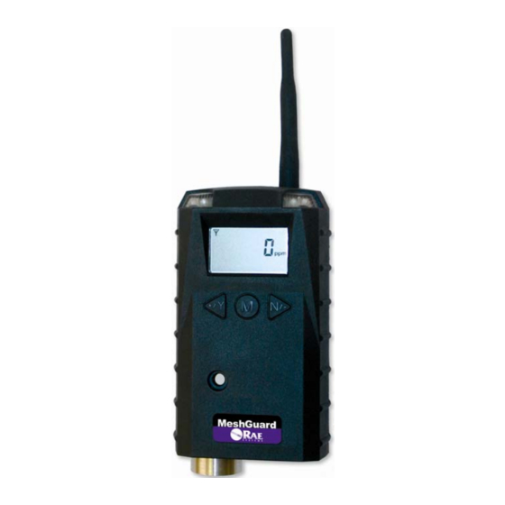
MeshGuard User’s Guide 3 Physical Description LED alarm Buzzer alarm Sensor gas inlet Battery cover Y/+, MODE, and N/- keys Antenna Not visible Optional magnetic mount on rear... -
Page 9: Lcd Display
MeshGuard User’s Guide LCD Display Zero Calibration Low Battery Indicator if on, the monitor is Wireless Communication ( in RDF; if blinking, the monitor is FFD) Short Term Exposure Limit (STEL) Time Weighted Average (TWA) 6, 8 High Alarm 7, 8... -
Page 10: Specifications
MeshGuard User’s Guide Specifications FCC Part15 CE EN 300328 Certifications SRRC(Pending) Display Customized LCD (1 x 1.5″) with backlight Audible alarm 90dB @ 30cm Visual alarm 2 super-bright red LEDs Calibration Two-point field calibration RF IEEE 802.15.4/Zigbee with mesh stack... -
Page 11: Operating The Meshguard
“F1.0” means firmware version 1.0, “F2.0” means firmware version 2.0, etc.): Then the MeshGuard initializes the wireless network and displays this information: Note: If MeshGuard is unable to find a radio network to connect with, it searches, and the display alternates between “rdo” and “Srh” (for “radio search”). -
Page 12: Turning The Meshguard Off
MeshGuard User’s Guide Next, the display tells you that MeshGuard is initiating network communication: Next, if a network is located, an antenna icon appears (if no network is found, then the icon is not shown; press [Y/+] to search for a network). -
Page 13: Low Battery Indicator & Action
When battery is completely depleted, the LCD displays “OFF,” and the LED, buzzer and vibration alarm activate once per second. The battery icon also blinks on and off. The MeshGuard shuts down after you press any key, or shuts down automatically if you do not press a key for 60 seconds. -
Page 14: Operation Modes
(the default is 30 seconds) or anytime an alarm occurs. In FFD mode, the MeshGuard receives data in real time, and it can also work as a router as needed to relay data from RFD devices back to the host. -
Page 15: Detection Mode
MeshGuard User’s Guide Detection Mode The MeshGuard can operate in fixed or portable mode. Whenever you start MeshGuard, it is automatically in fixed Detection Mode, which is the default. The MeshGuard displays the current reading: Pressing [MODE] steps through the Detection Mode screens:... - Page 16 Press [MODE] to return to the detector reading: Manually Sending Data While the MeshGuard typically sends reading data to the network on a fixed interval, you can send the data anytime. Press the [Y/+] key. The screen alternates between “Ini” and “nEt” one...
-
Page 17: Detection Mode (When Portable Mode Is Enabled)
MeshGuard User’s Guide Detection Mode (When Portable Mode Is Enabled) When Portable Mode is enabled (see page 32), pressing [MODE] steps through three more screens, STEL, TWA, and Peak:... - Page 18 Note: The STEL reading does not appear until 15 minutes have elapsed. If the MeshGuard has not been on for 15 minutes, it displays three dashes: Press [MODE], and it displays TWA. The TWA (time-weighted average) is the accumulated reading of the gas concentration, divided by 8 hours, since the monitor was turned on.
-
Page 19: Programming Mode
MeshGuard User’s Guide Press [MODE] to return to the current reading: Programming Mode Programming Mode allows you to perform any of the following actions (listed in order of appearance): • Calibrate the MeshGuard • Changing Preset Limits or Span Gas Values The menus accessed in Programming Mode are: •... -
Page 20: Entering Programming Mode
Each display alternates between its name and a status message or value. Note: You can exit Programming Mode at any time by pressing [MODE]. Also, if you do not make a change within one minute, the MeshGuard exits Programming Mode and returns to Detection Mode. -
Page 21: Exiting Programming Mode
1. Press [MODE]. MeshGuard exits Program Mode and shows the current reading in Detection Mode. 2. Do not press any buttons for 1 minute. MeshGuard automatically exits Programming Mode and returns to Detection Mode, showing the current reading. -
Page 22: Changing Values
MeshGuard User’s Guide 5.3.3 Changing Values When an editable numerical value is shown, the most significant digit flashes: Change the value by pressing [Y/+] to increase it, and [N/-] to decrease it. Press [MODE] to advance to the next digit: After editing the last digit, press [MODE]. - Page 23 MeshGuard User’s Guide Press [Y/+] for “yes.” The message “dn” indicates the change is done. Press [N/-] for “no.” A “no” message means that the change was abandoned. Press [MODE] to return to the first digit and continue editing values for...
-
Page 24: Zero Calibration
MeshGuard User’s Guide 5.3.4 Zero Calibration When “CAL” and “go” are displayed in alternation, and “ZERO” is shown, the MeshGuard is ready to perform a zero calibration. Press [Y/+]. The LCD displays “go.” The display counts down from 10 to 0. -
Page 25: Span Calibration
MeshGuard is now ready to perform a span calibration. To start calibration, press [Y/+]. The LCD displays “go.” The MeshGuard waits for 10 seconds so that you have time to connect the span gas. Connect the calibration gas adapter to the MeshGuard, and... - Page 26 MeshGuard User’s Guide When the gas flow starts, the LCD displays “gAS” and the span concentration value. The MeshGuard now counts down to 0. Note: The countdown time varies according to the type of sensor used in the MeshGuard. After counting down and reaching 0, the LCD displays “dn.” The reading should be the span concentration value.
- Page 27 MeshGuard User’s Guide If the MeshGuard does not detect gas after counting down to 0, the LCD displays “Err” (for “error”). The LED glows red and the buzzer sounds to provide extra warning. The MeshGuard automatically returns to the span calibration display.
-
Page 28: Change High Alarm
MeshGuard User’s Guide 5.3.6 Change High Alarm At the menu for changing the High Alarm setting, “ Set” and “ go” flash in alternation, and both “HIGH“ and “ALARM” are shown. Press [Y/+] to enter and change the setting. Press [MODE] to go back to Detection Mode or [N] to advance to the next menu. -
Page 29: Change Low Alarm
MeshGuard User’s Guide 5.3.7 Change Low Alarm At the Change Low Alarm menu, “Set” and “go” flash in alternation, and “LOW“ and “ALARM” are visible in the display. Press [Y/+] to enter and change the setting. Press [MODE] to exit and return to Detection Mode or [N] to advance to the next menu. -
Page 30: Change Stel Setting (Portable Mode Only)
MeshGuard User’s Guide 5.3.8 Change STEL setting (Portable Mode Only) Note: This menu is only available when the MeshGuard is in Portable Mode. If it is in Fixed Mode, you will not see this menu and cannot change its settings. -
Page 31: Change Twa Setting (Portable Mode Only)
MeshGuard User’s Guide 5.3.9 Change TWA setting (Portable Mode Only) Note: This menu is only available when the MeshGuard is in Portable Mode. If it is in Fixed Mode, you will not see this menu and cannot change its settings. -
Page 32: Change Span Value
MeshGuard User’s Guide 5.3.10 Change SPAN value “Set” and “go” flash in alternation, and “SPAN” and a gas cylinder icon are shown. Press [Y/+] to enter and change the setting, [MODE] to exit and return to Detection Mode, or [N/-] to advance to the next menu. -
Page 33: Fixed Or Portable Operation Selection
In Portable Mode, STEL, TWA, and Peak readings are included. “SEt” and “ Ptb” flash in alternation, to indicate that the MeshGuard can now be set as fixed or portable. The default value is “fixed.” Press [Y/+] to enter and change the setting, [MODE] to exit and return to Detection Mode, or [N/-] to go to the next menu. -
Page 34: Change Communication Interval
MeshGuard User’s Guide Press [Y/+] to enter and change the setting, [MODE] to exit and return to Detection Mode, or [N/-] to go to the next menu. The LCD displays the current value (enabled or disabled). Change the value if necessary. -
Page 35: Diagnostic Mode
6 Diagnostic Mode Diagnostic Mode provides raw data from sensors and about settings. Entering Diagnostic Mode Note: To enter Diagnostic Mode, you must begin with the MeshGuard turned off. Press and hold [Y/+] and [MODE] until the MeshGuard starts. The instrument goes through a brief startup, and then displays “dIA” to indicate it is in Diagnostic Mode. -
Page 36: Exiting Diagnostic Mode
MeshGuard User’s Guide Exiting Diagnostic Mode Note: You can exit Diagnostic Mode and enter Programming Mode and calibrate the MeshGuard as usual by pressing both [MODE] and [N/-] for three seconds. Note: You can exit Diagnostic Mode and enter Detection Mode by pressing [MODE] and [Y/+] together for three seconds, or by turning it off and on again. -
Page 37: Zero Raw Count
Enable/disable audible and visible alarms • Select the sensor type Note: When the MeshGuard is in this programming mode, if you do not make a change or press a key for 60 seconds, it reverts to the standard Diagnostic Mode. - Page 38 MeshGuard User’s Guide Enter this programming mode by first entering Diagnostic Mode. This requires starting the MeshGuard while holding Y/+ and [MODE]. When you see the Sensor Raw Count screen, hold [MODE] and N/- until you see “Pro” in the display, indicating that you are in Programming Mode.
-
Page 39: Change Pan Id
When it is done, it alarms once and displays “dn” for “done.” 6.4.4 Factory Setting Press [Y/+] to return the MeshGuard to its original factory settings. 6.4.5 Audible & Visible Alarm Enable/Disable Press [Y/+] to toggle between the MeshGuard’s audible and visible alarms turned on and off. -
Page 40: Sensor And Battery Replacement
4. Replace the battery cover by turning it clockwise with the 3-pin end of the tool. Note: Only Change battery in a safe location and use the battery RAE Systems provided, model ER34615 or XL-205F. After changing the battery, wait at least 60 seconds before turning the MeshGuard on. -
Page 41: Sensor Filter Replacement
MeshGuard User’s Guide Battery Battery cover Sensor Filter Replacement 1. Use the 3-pin end of the tool to unscrew and open the filter holder by turning it counterclockwise. Filter Filter holder 2. Remove and discard the filter. 3. Place a new filter inside the monitor. -
Page 42: Sensor Replacement
3. Pull the old sensor out. 4. Gently push a new sensor into the compartment. Important! Ensure that the RAE Systems part number matches the sensor that was removed. WARNING! Use only the same sensor model as the one installed when the monitor was purchased. -
Page 43: Troubleshooting
MeshGuard User’s Guide 8 Troubleshooting Failure Symptom Cause Solution Cannot turn on Battery charge too low Replace battery Battery has been Wait at least 60 changed seconds to turn on MeshGuard New battery needs to Check RAE Systems be discharged before... -
Page 44: Alarm Signal Summary
The controller or controller or reader. reader’s network has Perform the network changed. searching function in diagnostic mode. The MeshGuard is out Move the MeshGuard of its RF range. close to a working controller or reader and Press [Y/+] Battery is low... - Page 45 MeshGuard User’s Guide 1 beep > TWA setting second 1beep > STEL STEL Setting second 1 beep Zero Drift < 0 ppm second 1 beep Battery Low < 3.2V minute 1 beep Battery < 3.1V Exhausted second...
-
Page 46: Warnings
Warning: Use only the Lithium battery provided by RAE Systems. This instrument has not been tested in an explosive gas/air atmosphere having an oxygen concentration greater than 21%. Substitution of components may impair suitability for intrinsic safety. -
Page 47: Installation
Installation Two methods for mounting MeshGuard make it easy to install. The first method uses a magnet that screw onto the rear of the Meshguard, making ideal for moving from one location to another. The second method uses a specially designed stainless-steel enclosure that is permanently mounted. -
Page 48: Fixed Installation
MeshGuard User’s Guide 11.2 Fixed Installation Four reinforced holes in the rear of the enclosure allow for a screw to pass through to the mounting brackets. Mounting Holes Side Front View View Sensor Cover The enclosure can be mounted to a vertical or horizontal pole. - Page 49 MeshGuard User’s Guide Slip the screws through the two holes that are side by side in order to mount the enclosure to a vertical pole. Otherwise slip the screws through the two vertically aligned holes to attach the enclosure to a horizontal pole.
- Page 50 Note: The sensor cover on the bottom of the enclosure can be removed so that the filter and sensor can be inspected without removing the MeshGuard from the enclosure. Simply pull off the cover and follow the maintenance procedures in this guide.
-
Page 51: Magnetic Mount Alternative Installation
MeshGuard User’s Guide 11.3 Magnetic Mount Alternative Installation The magnet-mount disc can be attached to the steel enclosure instead of the clamps. This approach provides the protection of the enclosure with the ease of installation afforded by the magnetic mounting. - Page 52 RAE Systems World Headquarters 3775 N. First St. San Jose, CA 95134-1708 USA Phone: 408.952.8200 Fax: 408.952.8480 E-mail: customerserv@raesystems.com Web Site: www.raesystems.com Rev. A July 2008 P/N D01-4002-000...
Need help?
Do you have a question about the MeshGuard and is the answer not in the manual?
Questions and answers