Table of Contents
Advertisement
Quick Links
Advertisement
Table of Contents

Related Manuals for Rae IAQRAE PGM-5210


Summary of Contents for Rae IAQRAE PGM-5210
- Page 1 IAQRAE PGM-5210 INDOOR AIR QUALITY MONITOR Operation & Maintenance Manual Document Number: 049-4003-000 Revision B, May 2005 This product may be covered by one or more of the following U.S. Patents: 5,393,979 5,561,344 5,773,833 6,225,633 6,313,638 6,333,632 6,320,388...
- Page 3 - READ BEFORE OPERATING - This manual must be carefully read by ALL individuals who have or will have the responsibility for using, maintaining, or servicing this product. The product will perform as designed only if it is used, maintained, and serviced in accordance with the manufacturer's instructions.
- Page 4 WARNINGS Use only RAE Systems battery packs designed for the IAQRAE Monitor (PGM-5210). This instrument is designed for use in ordinary locations only! STATIC HAZARD: Clean only with a damp cloth. For safety reasons this equipment must be operated and serviced by qualified personnel only.
- Page 5 être dangereuse. La calibration de toute instruments de RAE Systems doit être testé en exposant l’instrument à une concentration de gaz connue par une procédure dietalonnage avant de mettre en service l’instrument pour la première fois.
-
Page 7: Table Of Contents
TABLE OF CONTENTS 1. General Information 1.1 General Specifications 2. Operation of IAQRAE 2.1 Physical Description 2.2 Keys and Displays 2.3 Turn Power On/Off 2.4 Data Protection 2.5 Normal Mode Operation 2.6 Alarm Signals 2-11 2.7 Backlight 2-13 2.8 Alarm Limits and Calibration 2-14 2.9 Integrated Sampling Pump 2-15... - Page 8 TABLE OF CONTENTS 4.5.2 Change User ID 4-24 4.5.3 Change Alarm Mode 4-25 4.5.4 Change User Mode 4-26 4.5.5 Change Real Time Clock 4-27 4.5.6 Change Light and Buzzer Mode 4-28 4.5.7 Change Password 4-29 4.5.8 Change Pump Duty Cycle 4-30 4.5.9 Change Display Language 4-31...
- Page 9 INDEX OF TABLES AND FIGURES Table Title Page Range, Resolution & Response Time Key Functions During Normal Operation Alarm Signal Summary 2-12 Alarm Limits and Calibration 2-17 Programming Mode Functions Programming Keys Critical Parameters Figure Title Page Front View – Main Components Back View –...
-
Page 11: General Information
GENERAL INFORMATION 1. General Information The IAQRAE multi-gas monitor is a portable instrument that provides real time measurements and activates alarm signals when exposure exceeds preset limits. The programmable monitor contains up to five sensors that will monitor volatile organic compounds (VOC) gas, a toxic gas, carbon dioxide, humidity and temperature for measurements of Indoor Air Quality (IAQ). -
Page 12: General Specifications
GENERAL INFORMATION 1.1 General Specifications Table 1.1 IAQRAE Monitor Specification 9.25” L x 5.0” W x 9.25” H Dimensions (23.5cm L x 12.7cm x 23.5cm) 8.9 lbs (4.03 kg) with battery Weight Up to five sensors: Detectors • PID Sensor w/ 3/8 od 10.6 eV lamp •... - Page 13 GENERAL INFORMATION Flashing red LED cluster to indicate Audible Alarm exceeded preset limits, low battery, or sensor failure Two point field calibration for fresh air Calibration and standard reference gas (except for the temperature sensor) Shoulder strap, optional tripod/wall Attachments mounting bracket Internal integrated diaphragm pump Sampling Pump...
-
Page 14: Range, Resolution & Response Time
GENERAL INFORMATION Table 1.1 Range, Resolution & Response Time (t Sensor Range Resolution 0-9.99 ppm 0.01 ppm 10 seconds 10.0-99.9 ppm 0.1 ppm 100-999 ppm 1 ppm 0-20,000 ppm 10 ppm 60 seconds 0-500 ppm 1 ppm 25 seconds 0-100 ppm 1 ppm 30 seconds 0-20.0 ppm... -
Page 15: Operation Of Iaqrae
OPERATION OF IAQRAE 2. Operation of IAQRAE The IAQRAE multi-gas exposure monitor is a compact, portable instrument that provides real time measurements and activates alarm signals when exposure exceeds preset limits. Prior to factory shipment, the IAQRAE is preset with default alarm limits, and sensors are pre-calibrated with standard calibration gas. -
Page 16: Physical Description
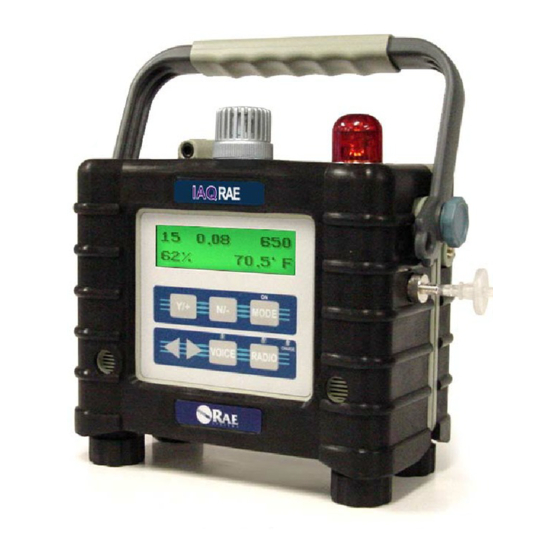
OPERATION OF IAQRAE 2.1 Physical Description Figure 2-1 Front View - Main Components of IAQRAE 1. Audible Alarm Port 2. Keypad [MODE] – operation key & programming key [Y/+] – operation & programming key [N/-] – operation & programming key [RADIO] –... -
Page 17: Back View – Main Components
OPERATION OF IAQRAE Figure 2-2 Back View - Main Components of IAQRAE 1. Battery pack - IAQRAE monitors are equipped with interchangeable rechargeable Lithium-Ion and alkaline battery packs 2. Gas exit port 3. Charger port – power jack connects IAQRAE to external DC for charging 4. -
Page 18: Keys And Displays
OPERATION OF IAQRAE 2.2 Keys and Display Display 0.00 R.H. 21°C On / Off Mode Key MODE LED Alarm & Charge Status CHARGE RADIO VOICE Not used Figure 2-3 IAQRAE Display and Keypad Table 2.1 Key Functions During Normal Operation Function Turn power on/off [MODE]... -
Page 19: Turn Power On/Off
OPERATION OF IAQRAE 2.3 Turn Power On/Off The Charge LED at the front of the monitor will light up when the monitor is plugged into the AC charger. When the LED is red, the battery is still charging. When the LED is green, the battery is fully charged and IAQRAE is ready for use. -
Page 20: Data Protection
OPERATION OF IAQRAE 2.4 Data Protection When the monitor is turned off, all the current real time data including peak, minimum, and elapsed time are erased. However, the datalogged data are preserved in non-volatile memory. Even if the battery is disconnected, the datalogged data will not be lost. -
Page 21: Normal Mode Operation
OPERATION OF IAQRAE 2.5 Normal Mode Operation The IAQRAE offers two levels of user operation: 1. Basic The monitor will display the sensor name after the monitor is turned on. Press [MODE] to view the functions illustrated in the round robin sequence. The user may enter Calibration Mode to perform calibrations, but may not change the other parameters. - Page 22 OPERATION OF IAQRAE Definitions of Basic and Advanced Functions 1. The Instantaneous Reading / Sensor Name function alternately displays the instantaneous reading and the sensor name. The instantaneous reading is the actual gas concentration in parts per million (ppm) for carbon dioxide, toxic or VOC gases, % RH for humidity, and Celsius (˚C) or Fahrenheit (˚F) for temperature.
- Page 23 OPERATION OF IAQRAE 5. The Battery Voltage is the current battery voltage (V) reading. The reading is updated every second and is shown with the shut off voltage: Battery = 7.4V Shut Off at 6.4V Note: A fully charged battery pack should show 7.7 volts or higher.
- Page 24 OPERATION OF IAQRAE 9. Communicate with PC? allows the user to upload data from the IAQRAE to their PC or download configuration information from a PC to the IAQRAE. Press [Y/+] and the message “Datalog Paused…” reminds the user that during PC communication there is no real time monitoring.
-
Page 25: Alarm Signals
OPERATION OF IAQRAE 2.6 Alarm Signals The built-in microprocessor continually updates and monitors gas concentrations. It also compares the readings with programmed low and high instantaneous gas concentration alarm limit settings. When the concentration exceeds any of the preset limits, the buzzer and red LED will immediately warn the user of the alarm condition. -
Page 26: Alarm Signal Summary
OPERATION OF IAQRAE Table 2.2 Alarm Signal Summary Message on Condition Alarm Signal LCD Screen Gas exceeds 3 beeps & flashes “High” High Alarm limit per second Gas exceeds 2 beeps & flashes “Low” Low Alarm limit per second 3 beeps & flashes Negative Drift “NEG”... -
Page 27: Backlight
OPERATION OF IAQRAE 2.7 Backlight The LCD is equipped with a backlight to assist reading under poor lighting conditions. When the monitor is in normal operation, the backlight may be manually turned on by pressing and holding [N/-] for one second. Press [N/-] a second time to turn off. -
Page 28: Alarm Limits And Calibration
OPERATION OF IAQRAE 2.8 Alarm Limits & Calibration IAQRAE is factory calibrated with standard calibration gas, and is programmed with default alarm limits as listed below. (See Section 4.2 Calibration and Section 4.3 Change Alarm Limits) Sensor Cal Gas / Balance Unit High 5000 / N... -
Page 29: Integrated Sampling Pump
OPERATION OF IAQRAE 2.9 Integrated Sampling Pump The IAQRAE includes an internal integrated sampling pump with programmable high and low pump speed settings: A low pump speed of ~300 cc per minute is the factory default. This rate increases battery life by about 5%. (See Section 4.5.9 Change Pump Speed). - Page 30 PID-cleaning, because the self-contained sensor cannot be manually cleaned. Unlike some other RAE products, the self-cleaning function is not operative when the unit is turned off and plugged into the charger. Self-cleaning is best performed by turning the unit on in normal operating mode, setting it in a clean environment (<2...
-
Page 31: Datalogging
OPERATION OF IAQRAE 2.10 Datalogging The IAQRAE Multi-Gas Monitor calculates and stores gas readings based on the user-specified datalogging period and type of measurement. Two types of gas measurements, average or peak concentration may be stored for each sensor for any datalogging interval. Datalogging intervals may be programmed from one second to sixty minutes in one-second increments. - Page 32 OPERATION OF IAQRAE Other Datalog options will automatically start and stop: Datalogging Event Each time a datalogging operation is initiated, a datalog event is created. Information, such as start time, datalogging period, alarm limits, etc. are recorded in the event header, followed by the measurement data.
-
Page 33: Operation Of Accessories
OPERATION OF ACCESSORIES 3. Operation of Accessories The accessories for IAQRAE include: • Wall mount AC adapter for charging battery • Li-Ion battery pack • Alkaline battery adapter • Water trap filter • Remote sampling probe • Calibration adapter WARNING To reduce the risk of ignition of hazardous atmospheres, recharge battery only in area known to be non-hazardous. -
Page 34: Interchangeable Battery Packs
OPERATION OF ACCESSORIES 3.1 Interchangeable Battery Packs WARNING To reduce the risk of ignition of hazardous atmospheres, recharge battery only in an area known to be non-hazardous. Remove and replace battery only in area’s known to be non- hazardous. When the display shows a flashing message “Bat”, the battery requires recharging. - Page 35 OPERATION OF ACCESSORIES Recharging the Lithium-Ion Battery Pack 1. Turn IAQRAE off. 2. The charging circuit of the IAQRAE is built into the monitor. It requires a regular AC to 15V DC adapter (a wall mount transformer) to charge the monitor. 3.
-
Page 36: Water Trap Filter
OPERATION OF ACCESSORIES 3.2 Water Trap Filter ® The external water trap/dust filter is made of a PTFE (Teflon membrane with a 0.2 micron pore size to prevent liquid water from being sucked into the sensor manifold, which would cause extensive damage to the monitor. -
Page 37: Remote Sampling Probe Or Teflon Tubing
OPERATION OF ACCESSORIES 3.3 Remote Sampling Probe ® or Teflon Tubing ® A 15-foot (5M) length of Teflon tubing is supplied as a standard accessory with every IAQRAE detector. An optional ® 6-foot Teflon remote sampling probe with a telescoping handle is also available for hard-to-reach areas such as ceilings, storage tanks, underground manholes, etc. -
Page 38: Calibration Adapter
OPERATION OF ACCESSORIES 3.4 Calibration Adapter The IAQRAE should be calibrated with the external water trap/dust filter in place. The IAQRAE calibration adapter is designed to slip over the filter. During calibration, connect the calibration adapter to the cylinder of the calibration gas. Then insert adapter into filter and allow the gas to flow to sensors. -
Page 39: Programming Iaqrae
PROGRAMMING OF IAQRAE 4. Programming of IAQRAE The IAQRAE is built with a microprocessor to provide programming flexibility for the user. The user may access the programming functions depending on the user operation level and the security level. (See Table 4.1 Programming Mode Functions) There are two levels of user operation: Basic and Advanced. -
Page 40: Programming Mode Functions
PROGRAMMING OF IAQRAE Table 4.1 Programming Mode Functions User Operation Level Basic Advanced Security Level Calibrate Monitor? Fresh Air Calibration? Multiple Sensor Calibration? Single Sensor Calibration? Modify Span Gas Value? Change VOC Span Gas? Change Alarm Limit? Change High Alarm Limit? Change Low Alarm Limit? Change Datalog Setting? Clear All Data? -
Page 41: Enter And Exit Programming Mode
PROGRAMMING OF IAQRAE 4.1 Enter & Exit Programming Mode Table 4.2 Programming Keys Exit menu when pressed momentarily [MODE] Exit data entry mode when pressed and held for one second Increase numerical value for data entry [Y/+]* Answer “yes” Decrease numerical value for data entry [N/-]* Answer “no”... - Page 42 PROGRAMMING OF IAQRAE 7. If the entered password is correct, the monitor enters the programming menu. The first menu item “Calibrate Monitor?” will display. 8. If the password is incorrect, the display shows “Wrong Password???” and returns to the regular display of instantaneous gas readings.
-
Page 43: Calibration Menu
PROGRAMMING OF IAQRAE 4.2 Calibration Menu WARNING The calibration of all newly purchased RAE Systems instruments should be tested by exposing the sensor(s) to known concentration calibration gas before the instrument is put into service for the first time. For maximum safety, the... - Page 44 PROGRAMMING OF IAQRAE The CO2 sensor zeroing requires a CO2-free gas source, such as a cylinder of dry air, nitrogen, or 10 ppm isobutylene. The CO2 sensor is typically spanned with 5,000 ppm CO2. The RH and temperature sensor s need far less frequent calibration than the other sensors.
-
Page 45: Fresh Air Calibration
PROGRAMMING OF IAQRAE 4.2.1 Fresh Air Calibration This procedure determines the zero point of the sensor calibration curve for the PID and toxic gas sensor. The CO2, RH, and temperature sensors must be zeroed in the single sensor calibration menu. To perform fresh air calibration, one of the zero gas options described in the previous section should be used. -
Page 46: Multiple Sensor Calibration
PROGRAMMING OF IAQRAE 4.2.2 Multiple Sensor Calibration This function simultaneously determines the second point of the calibration curves for multiple sensors in the monitor. Mixed standard reference gases are needed to perform this procedure. The user may choose several gas mixtures to be used in multiple sensor calibration. - Page 47 PROGRAMMING OF IAQRAE 3. This completes the Multiple Sensor Calibration procedure and moves to the next submenu item, Single Sensor Calibration. 4. Turn off gas flow. Disconnect calibration tube from monitor. 5. If the sensor failed the calibration, the sensor name and an error message “failed”...
-
Page 48: Single Sensor Calibration
PROGRAMMING OF IAQRAE 4.2.3 Single Sensor Calibration This procedure determines the second point of the sensor calibration curve for a single sensor. A standard reference gas (span gas) is needed to perform this procedure. Table 2.2 (Alarm Limits and Conditions) shows the standard calibration gas which is typically used as the span gas at the factory. - Page 49 PROGRAMMING OF IAQRAE 6. Turn gas flow off. Disconnect calibration tube from monitor. Calibration Time Stamp When a single sensor calibration is performed, a time stamp will be stored in nonvolatile memory. This information will be included in the Datalogging report. Sensor Calibration sensor calibration is different from calibrating other sensors.
-
Page 50: Water Bubbler Connections For Span Cal
PROGRAMMING OF IAQRAE Relative Humidity Sensor Calibration Calibrating the Relative Humidity (RH) sensor is different from calibrating other sensors. The RH sensor requires for less frequent calibration than other chemical sensors. Under normal conditions annual calibration may be adequate. During single sensor calibration, the user needs to supply dry gas (<10%) to zero the sensor. -
Page 51: Modify Span Gas Value
PROGRAMMING OF IAQRAE 4.2.4 Modify Span Gas Value This function allows the user to change the span values of the standard calibration gases. 1. When the “Modify Span Gas Value?” screen appear, press [Y/+], and a list of enabled sensors will appear: Temp Use [MODE] to select the desired sensor, and the cursor will advance to the next sensor;... -
Page 52: Change Voc Span Gas
PROGRAMMING OF IAQRAE 4.2.5 Change VOC Span Gas This function allows the user to select a specific VOC gas to be used as the span gas during VOC gas calibration. If a span gas other than isobutylene is used, the correction factor (CF) for the measurement gas will be divided by the CF for the new span gas to obtain a modified factor for the measurement gas. -
Page 53: Change Alarm Limits
PROGRAMMING OF IAQRAE 4.3 Change Alarm Limits The user may change the high or low alarm limits for each sensor in Programming Mode. The submenus are: Change High Alarm limit? Change Low Alarm limit? 1. Press [N/-] to toggle between these two submenus. When the “Change High Alarm?”... -
Page 54: Change Datalog Setting
PROGRAMMING OF IAQRAE 4.4 Change Datalog Setting The IAQRAE calculates and stores the gas readings at a specified interval. The user may review these stored readings, change the datalog setup, or program additional datalog options by downloading from PC to IAQRAE using ProRAE Suite software. -
Page 55: Clear All Data
PROGRAMMING OF IAQRAE 4.4.1 Clear All Data This function will erase all data stored in the non-volatile datalog memory. This does not change peak or minimum concentration or run time values stored in other locations. 1. When the “Clear All Data?” screen appears, press [Y/+] to clear the data memory. -
Page 56: Change Datalog Period
PROGRAMMING OF IAQRAE 4.4.2 Change Datalog Period The datalog period can be programmed from 1 to 3,600 seconds (1 hour). 1. When the “Change Datalog Period?” screen appears, press [Y/+], and the display “Datalog Period = 60” will appear; “60” is the previously stored datalog period. 2. -
Page 57: Select Datalog Mode
PROGRAMMING OF IAQRAE 4.4.3 Select Datalog Mode Datalogging may be initiated in one of four ways: Periodic: Set a recurring start and stop time that repeats every day when the unit is on. Scheduled: Datalogging starts and stops automatically for one set moment. -
Page 58: Enable/Disable Datalog
PROGRAMMING OF IAQRAE 4.4.4 Enable/Disable Datalog The user may enable or disable the datalogging function for each sensor. This allows the user to selectively log certain sensor readings of interest. 1. When the “Enable/Disable Datalog?” appears, press [Y/+]. The display will show all enabled sensors installed in the monitor. -
Page 59: Select 'Memory Full' Type
PROGRAMMING OF IAQRAE 4.4.5 Select ‘Memory Full’ Type There are two options for the user when the datalog memory becomes full. The Stop selection automatically stops datalogging once the memory is full. The Wrap-Around selection overwrites the oldest data as the monitor continues datalogging. -
Page 60: Change Monitor Setup
PROGRAMMING OF IAQRAE 4.5 Change Monitor Setup The user may change the monitor setup or enter user information for the IAQRAE monitor. The Monitor Setup submenus are listed below: Change Site ID? Change User ID? Change Alarm Mode? Change User Mode? Change Real Time Clock? Change Light and Buzzer Mode? Change Password? -
Page 61: Change Site Id
PROGRAMMING OF IAQRAE 4.5.1 Change Site ID The user may enter an eight-character site ID, which will be included in the datalog report. 1. At the “Change Site ID?” screen, press [Y/+] and the display will have the current site ID: “Site ID = xxxxxxxx”. Press [MODE] to move the cursor to the left-most digit. -
Page 62: Change User Id
PROGRAMMING OF IAQRAE 4.5.2 Change User ID The user may enter an eight-character user ID, which will be included in the datalog report. 1. At the “Change User ID?” screen, press [Y/+] and the display will have the current user ID: “User ID = xxxxxxxx”. Press [MODE] to move the cursor to the left-most digit. -
Page 63: Change Alarm Mode
PROGRAMMING OF IAQRAE 4.5.3 Change Alarm Mode There are two different alarm modes in IAQRAE: Auto-Reset and Latched. In Auto-Reset mode, the alarm automatically turns off when the alarm condition no longer exists (e.g. the gas concentration falls below the lower alarm limit). In Latched mode, the alarm remains on even after the alarm condition no longer exists. -
Page 64: Change User Mode
PROGRAMMING OF IAQRAE 4.5.4 Change User Mode There are two different user operation levels (or modes): Basic and Advanced. The Advanced Mode allows user access to all programming functions, whereas Basic Mode limits access to certain Calibration and Monitor Setup functions. See Table 4.1 for a detailed list of functions accessible in the two modes. -
Page 65: Change Real Time Clock
PROGRAMMING OF IAQRAE 4.5.5 Change Real Time Clock The IAQRAE monitor is equipped with a real time clock, which the user may change when needed. 1. When the “Change Real time Clock?” screen appears, press [Y/+], and the display will show the current date and time: “16 Apr ’02 04:52”. -
Page 66: Change Light And Buzzer Mode
PROGRAMMING OF IAQRAE 4.5.6 Change Light and Buzzer Mode The user has the option to turn the light and buzzer on/off to suit their needs. The factory default setting is saved to have both the light and buzzer turn on during alarm conditions. 1. -
Page 67: Change Password
PROGRAMMING OF IAQRAE 4.5.7 Change Password The user can modify the password from the monitor. 1. When the “Change Password?” screen appears, press [Y/+] and the display will show the current password: Password = 0000 Save? 2. Press [MODE] to move the cursor from “Save?” to the left digit. -
Page 68: Change Pump Duty Cycle
PROGRAMMING OF IAQRAE 4.5.8 Change Pump Duty Cycle The duty cycle function allows the user to control the time the pump is one for a specified ten-second period. A 70% duty cycle means that the instrument turns the pump on for seven seconds, and then turns the pump off for three seconds. -
Page 69: Change Display Language
PROGRAMMING OF IAQRAE 4.5.9 Change Display Language Users may choose to view the display menus in English or Spanish. Additional languages may be added in the future. 1. When the “Change Display Language?” screen appears, press [Y/+] to display the current Language “Display Language = English?”... -
Page 70: Set Temperature Unit
PROGRAMMING OF IAQRAE 4.5.10 Set Temperature Unit The user may set the temperature unit to either Fahrenheit to Celsius (factory setting). 1. At the “Temperature Unit = Celsius?” display, press [N/-] to toggle between Fahrenheit and Celsius. 2. Press [Y/+] or [MODE] to accept new settings and advance to the next menu option. -
Page 71: Change Sensor Configuration
PROGRAMMING OF IAQRAE 4.6 Change Sensor Configuration The user may change several sensor related configurations. The Change Sensor Configuration contains the following configuration options: Change VOC Measurement Gas? Edit Correction Factor? Enable/Disable Sensors? Change Custom Gas Name? Correction Factors The PID sensor used in IAQRAE responds to a broad range of gases. -
Page 72: Change Voc Gas Selection
PROGRAMMING OF IAQRAE 4.6.1 Change VOC Gas The user may choose one of the pre-stored VOC gases in the monitor, which then automatically calculates its correction factor relative to the VOC calibration gas. This correction factor is used during gas measurements calculate and display the equivalent concentration of the selected VOC gas. -
Page 73: Edit Correction Factors
PROGRAMMING OF IAQRAE 4.6.2 Edit Correction Factor The user can modify the correction factor from the monitor. 1. When the “Edit Correction Factor?” screen appears, press [Y/+] the display shows the current correction factor: Correction Factor= Save? 2. Press [MODE] to move the cursor from “Save?” to the left digit. -
Page 74: Enable/Disable Sensor
PROGRAMMING OF IAQRAE 4.6.3 Enable/Disable Sensor This function allows the user to selectively enable or disable individual sensors in the IAQRAE monitor. When a sensor is disabled, the sensor still measures the gas but no values are displayed and all alarms for that sensor are rendered non- functional. -
Page 75: Change Custom Gas Name
PROGRAMMING OF IAQRAE 4.6.4 Change Custom Gas Name This function allows the user to enter a custom gas name. 1. When the “Custom Gas= Save?” screen appears, press [MODE] to advance the cursor from the “?” to the second line “Custom Gas”. Custom Gas= Save? Custom Gas... -
Page 77: Theory Of Operation
THEORY OF OPERATION 5. Theory of Operation The IAQRAE monitor uses one to five different sensors to measure a variety of gases. (See Figure 5-1.) A unique electrodeless discharge UV lamp is used as the high-energy photon source for the PID sensor. The patented PID sensor detects a broad range of organic vapors. - Page 78 THEORY OF OPERATION A single chip microprocessor is used to control the operation of the alarm buzzer, LED, pump and light sensor. It measures the sensor readings and calculates the gas concentrations based on calibration to known standard gases. The data are stored in non-volatile memory so they may be sent to a PC for record keeping.
-
Page 79: Maintenance
SENSOR AND PUMP MAINTENANCE 6. Maintenance Figure 6-1 Internal Structure of IAQRAE... -
Page 80: Sensor Replacement
IAQRAE monitor. The toxic gas sensor socket allows the user to plug in any of the toxic gas sensors offered by RAE Systems. (Note: The firmware recognizes all sensors except the ClO sensor.) -
Page 81: Detailed Sensor Assembly
SENSOR AND PUMP MAINTENANCE Sensor PID Sensor Sensor Mounting Gas Plate Screw Gas Plate PID Sensor Oxygen Sensor Pump Base Plate Humidity-Temp Sensor Figure 6-2 Detailed Sensor Assembly of IAQRAE 8. Turn IAQRAE on. The microprocessor will automatically recognize the sensors installed and configure the monitor accordingly. -
Page 82: Pid Sensor Maintenance
SENSOR AND PUMP MAINTENANCE 6.2 PID Sensor Maintenance This section only applies to IAQRAE monitors that are equipped with a PID sensor. During the course of normal operation, a film of gas vapor may build up inside the PID sensor module and the UV lamp. The rate at which the film develops depends on the type and concentration of the vapors being sampled. -
Page 83: Sampling Pump Replacement
SENSOR AND PUMP MAINTENANCE 6.3 Sampling Pump Replacement The sampling pump is positive displacement piston pump. When approaching the end of the specified lifetime of the pump, it will consume a higher amount of energy and reduce its sample draw capability significantly. When this occurs, it is necessary to replace the pump. -
Page 85: Troubleshooting
TROUBLESHOOTING 7. Troubleshooting To aid the user in diagnosing the monitor, a diagnostic mode can be used to display critical, low level parameters. Section 7.1 describes the operation of the Diagnostic Mode. Section 7.2 summarizes possible encountered problems and suggested solutions. -
Page 86: Diagnostic Mode
TROUBLESHOOTING 7.1 Diagnostic Mode To place the monitor into the special diagnostic mode, first turn the monitor off. Next simultaneously push and hold [Y/+] and [MODE] for at least two seconds. After the required delay, release both keys and the monitor will go through the normal start-up display sequence and display a “Diagnostic mode”... - Page 87 TROUBLESHOOTING Diagnostic displays and how to interpret the displayed values: 1. Raw Sensor Readings The raw sensor readings provide a quick diagnose on the response and the sensitivity of each sensor. When zero gas (fresh clean air) is applied to the monitor, the raw sensor readings typically should be: 1000 to 2500 for the CO sensor...
- Page 88 TROUBLESHOOTING 3. PID Lamp Parameters This function applies to monitors equipped with a PID sensor. Drv is the lamp drive and is not adjustable from the standard value of 200. Lamp is the lamp current draw. Fail is an adjustable failure threshold. Use [N/-] and [Y/+] to set the Fail about 10 counts lower than the lamp reading.
- Page 89 TROUBLESHOOTING 6. Adjust LCD Contrast This display allows the user to adjust the LCD contrast. Press [Y/+] to increase contrast and [N/-] to decrease the contrast. The bar graph shows the current LCD contrast setting. If the display appears to have dark lines, press [Y/+] several times and a clearer display should appear: Contrast = 115 000 <...
- Page 90 TROUBLESHOOTING d. The pump stall threshold should be re-adjusted if the pump speed is switched to “low” or “high,” or water trap filter changed, or the firmware configuration has been totally refreshed. 8. Clock and Battery Voltage This display shows the real time clock and battery voltage in raw count.
-
Page 91: Possible Problems And Solutions
TROUBLESHOOTING 7.2 Possible Problems & Solutions Problem Possible Reason Possible Solution No power after Drained battery Charge battery charging battery Defective battery Replace battery Microprocessor Disconnect then hang-up reconnect battery to reset computer No LED or LCD Defective LED or Call authorized backlight LCD backlight... - Page 92 TROUBLESHOOTING Reading abnormally Incorrect calibration Calibrate monitor Low sensitivity to Replace sensor the specific gas Check sensor raw response in diagnostic mode Check gas flow path Low gas flow to for leaks; replace sensor(s) pump or pump diaphragm Read a small Sensor zero drifted Do fresh air background value...
- Page 93 TROUBLESHOOTING “Bat” message in Uncharged battery Recharge battery operation “Voltage too high” Battery fuse blown Check battery and message in charge adapter Incorrect fuse mode Plug adapter in AC adapter is not correctly plugged in all the Full scale PID Dirty or wet sensor Run dry gas through measurement in...
- Page 95 APPENDIX A Navigation Guide M: Press [MODE] M+Y: Press [MODE] and [Y/+] together M+N: Press [MODE] and [N/-] together M5: Press [MODE] for more than 3 seconds, then countdown for 5 seconds * If the unit is turned on in Diagnostic Mode, the user may switch between Diagnostic Mode and Normal Mode, by pressing [MODE] and [Y/+] together.
-
Page 96: Normal Mode: Display Menu
APPENDIX A Normal Mode: Display Menu Normal Mode XXXX XXXX XXXX Programming XXXX XXXX Mode XXXX XXXX XXXX XXXX PEAK XXXX XXXX XXXX XXXX XXXX MIN XXXX Reset Peak and Min(Y/N)? Clear Peak and Battery=7.4V Shut off at 6.4V Jun 21,'01 13:15 ON=00:00 Start/Stop Datalog? -
Page 97: Diagnostic Mode: Display Menu
APPENDIX A Diagnostic Mode: Display Menu Diagnostic Mode Programming XXXX XXXX XXXX Mode XXXX RAW XXXX PID Ref xxx xxx Y-next gain N-previous gain Drv Lamp Fail xxx xxx Y-increment N-decrement CO2 Ref Bias 1739 1865 *255 Y-increment N-decrement ToxA ToxB Bias *xxx Y-next bias N-previous bias... -
Page 98: Programming Mode: Calibration Menu
APPENDIX A Programming Mode: Calibration Menu Calibration Menu Calibrate Back to User Mode To Alarm Limt Menu Monitor? Fresh Air Calibration? Process Multiple Sensor Calibration? Process Single Sensor Calibration? Process Modify Span Gas Value? Process Change VOC Span Gas? Process... -
Page 99: Programming Mode: Alarm Limit Menu
APPENDIX A Programming Mode: Alarm Limit Menu Alarm Limit Menu Change Alarm Back to User Mode To Datalog Menu Limit? Change High Alarm Limit? Process Change Low Alarm Limit? Process... -
Page 100: Programming Mode: Datalog Menu
APPENDIX A Programming Mode: Datalog Menu Datalog Menu Change Datalog Back to User Mode To Monitor Setup Menu Setting? Clear All Data? Process Change Datalog Period? Process Select Datalog Mode? Process Enable/Disable Datalog? Process Select Memory Full Type? Process... -
Page 101: Programming Mode: Monitor Setup Menu
APPENDIX A Programming Mode: Monitor Setup Menu Monitor Setup Menu Change Monitor Back to User Mode To Sensor Config Menu Setup? Change Site ID? Process Change User ID? Process Change Alarm Mode? Process Change User Mode? Process Change Real Time Clock? Process Change Light and... -
Page 102: Programming Mode: Sensor Configuration Menu
APPENDIX A Programming Mode: Sensor Configuration Menu Sensor Config Menu Change Sensor Back to User Mode To Calibration Menu Configuration? Change VOC Gas (measurement)? Process Edit Correction Factor? Process Enable/Disable Sensor? Process Change Custom Gas Name Process... - Page 103 Correction factors for a number of commonly used compounds for the 10.6 eV PID sensors has been provided. A comprehensive list of correction factors is available at the RAE website www.raesystems.com, under Technical Note 106. VOC correction factors are measured relative to isobutylene gas.
- Page 104 APPENDIX B Compound CF at Compound CF at Ethyl hexyl acrylate, 2- Methyl ethyl ketone Ethyl sulfide Methyl isobutyl ketone Gasoline vapors Methyl methacrylate Gasoline, whole Methyl t-butyl ether Heptane, n- Nitric oxide Hexamethyldisilazane Octane, n- Hexane, n- Pentane Hydrazine Perchloroethene 0.57 Hydrogen...
- Page 106 RAE Systems, Inc. Main Office 3775 N. First St. San Jose, CA 95134-1708 USA Contact Numbers Telephone 408.952.8200 408.952.8480 Instrument Sales 877.RAE.CUSTOMER (877.723.2878) Tubes Sales 888.RAE.TUBE (888.723.8823) Technical Support 888.723.4800 E-mail RaeSales@raesystems.com Tech@raesystems.com Website www.raesystems.com Important Note: Before returning the unit for service or repair, please obtain a Return Material Authorization (RMA) Number for proper tracking of your equipment.
Need help?
Do you have a question about the IAQRAE PGM-5210 and is the answer not in the manual?
Questions and answers