
Subscribe to Our Youtube Channel
Related Manuals for Rae MiniRAE 2000 PGM-7600


Summary of Contents for Rae MiniRAE 2000 PGM-7600
- Page 1 MiniRAE 2000 Portable VOC Monitor PGM-7600 OPERATION AND MAINTENANCE MANUAL (Document No.: 011-4001-000) Revision E, May 2005...
- Page 2 B. Recharge batteries only in non-hazardous locations. C. Do not connect external cable to serial interface jack in hazardous locations. D. Use RAE Systems Adapter P/N 500-0072 for connection to communication port and charging jack only in a non- hazardous area.
-
Page 3: Table Of Contents
Table of Contents GENERAL INFORMATION ......1-1 General Specifications ..........1-2 OPERATION OF MINIRAE 2000 ....2-1 Physical Description ..........2-2 Keys and Display ............2-3 Power On/Off ............2-4 Operation..............2-5 2.4.1 Survey Mode ............2-6 2.4.2 Hygiene Mode ........... 2-14 Alarm Signals............ - Page 4 Change Alarm Limits..........4-15 4.5.1 Change Low Alarm Limit ......... 4-17 4.5.2 Change STEL Limit .......... 4-18 4.5.3 Change TWA Limit........... 4-19 View or Change Datalog......... 4-20 4.6.1 Reset Peak/Minimum ........4-21 4.6.2 Clear Data............4-223 4.6.3 Change Data Period........4-2324 4.6.4 Change Average Type ........
- Page 5 WARNING - Do NOT proceed before reading - This manual must be carefully read by all individuals who have or will have the responsibility for using, maintaining, or servicing this product. The product will perform as designed only if it is used, maintained, and serviced in accordance with the manufacturer's instructions.
- Page 6 Special Notes When the MiniRAE 2000 Monitor is taken out from the transport case and turned on for the first time, there may be some residual organic or inorganic vapor trapped inside the detector chamber. The initial PID sensor reading may indicate a few ppm.
- Page 7 Read and understand instruction manual completely before operating servicing. Use only RAE Systems battery packs, part nos. 012-3050, 012-3051 or 012-3052. This instrument has not been tested in an explosive gas/air atmosphere having an oxygen concentration greater than 21%.
- Page 8 Étudier le manuel d’instructions en entier avant d’utiliser, d’entretenir ou de réparer l’équipement. Utiliser seulement l'ensemble de batterie RAE Systems, la reference 012-3050, 012-3051 au 012-3052. Cet instrument n’a pas été essayé dans une atmosphère de gaz/air explosive ayant une concentration d’oxygène plus élevée que 21%.
-
Page 9: General Information
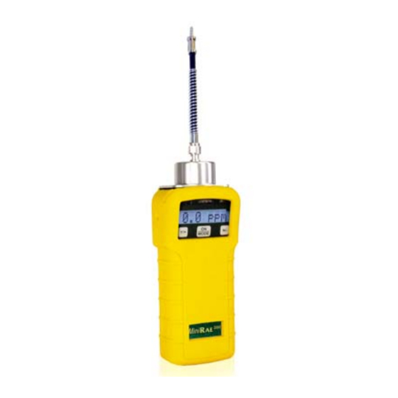
GENERAL INFORMATION GENERAL INFORMATION MiniRAE 2000 Portable VOC Monitor (Model PGM 7600) is a compact monitor designed as a broadband VOC gas monitor and datalogger for work in hazardous environments. It monitors Volatile Organic Compounds (VOC) using a Photo-Ionization Detector (PID) with a 9.8 eV, 10.6 eV, or 11.7 eV gas discharge lamp. -
Page 10: General Specifications
GENERAL INFORMATION 1.1 General Specifications Table 1.1 Portable VOC Monitor Specification Size: 8.2"L x 3.0"W x 2.0"H Weight: 19.5 oz with battery pack Detector: Photo-ionization sensor with 9.8, 10.6, or 11.7 eV UV lamp Battery: A 4.8V /1250 mAH Rechargeable Nickel Metal Hydride battery pack (snap in, field replaceable) Battery Charging: 10 hours charge through built-in charger... - Page 11 GENERAL INFORMATION Direct Readout: Instantaneous, average, STEL and peak value, battery voltage and elapsed time Intrinsic Safety: UL & cUL Class 1, Division I, Group A,B,C,D, Temperature Code T3C (US & Canada); 0575 II 1G DEMKO 02 ATEX 0204759 Eex ia IIC T4 (Europe) No effect when exposed to 0.43 W/cm 2 RF EM Interference: interference (5 watt transmitter at 12 inches)
-
Page 12: Operation Of Minirae 2000
OPERATION OPERATION OF MINIRAE 2000 The MiniRAE 2000 Portable VOC Monitor is a compact Monitor designed as a broadband VOC gas monitor and datalogger for work in hazardous environments. It gives real time measurements and activates alarm signals whenever the exposure exceeds preset limits. -
Page 13: Physical Description
OPERATION 2.1 Physical Description The main components of the MiniRAE 2000 Portable VOC monitor include: • Three keys for user to interact with the monitor: 1 operation key and 2 programming keys for normal operation or programming of the monitor •... -
Page 14: Keys And Display
OPERATION 2.2 Keys and Display Figure 2.2 shows the LCD display and the keypad on the front panel of the monitor. The function of the 3 keys during normal operation are summarized below: Alarm LED’s Light sensor Charge LED 0.0 ppm Figure 2-2 LCD Display and Keypad Function in Normal Operation [MODE] -Turn on/off the power* and step through menu items... -
Page 15: Power On/Off
OPERATION 2.3 Power On/Off To turn on the MiniRAE 2000 portable VOC monitor, press [MODE] key for one second and release. The audio buzzer will beep once and the air pump will turn on. The display will show “ON!..” and then “Ver n.nn” to indicate the unit’s current firmware version number. -
Page 16: Operation
OPERATION 2.4 Operation The MiniRAE 2000 VOC monitor has two operation modes: Survey and Hygiene mode. The Survey mode allows the user to manually start and stop the monitoring/measuring operation and display certain exposure values. In the Hygiene mode, the monitor runs continuously after the monitor is turned on. -
Page 17: Survey Mode
OPERATION 2.4.1 Survey Mode After the monitor is turned on, it runs through the start up menu. Then the message “Ready...” is displayed (see figure below). Ready… At this point, the user has two options: 1. Step through the Main Menu. 2. - Page 18 OPERATION The Main Menu Press the [MODE] button to enter the Main Menu. Press the [Y/+], [MODE] or [N/-] as indicated in the flow chart below to step through the Main Menu. The PID sensor and pump are turned off during this time. The Main Menu functions are: •...
- Page 19 OPERATION These functions are arranged in a “round robin” order. To select a specific function, press the button as shown below until the desired function appears. Main Menu...
- Page 20 OPERATION The Main Menu Functions • Ready…: Indicates that the monitor is ready to take a measurement or to step through the Main Menu. Press the [Y/+] button to advance to taking a measurement (read “Taking a Measurement” on Page 2-12 for details). Note: The Ready…...
- Page 21 OPERATION Note: This display appears only after a measurement has been started. It does not appear when the user is cyling through the Main Menu and the monitor is idling. • x.x ppm: (read “Taking a Measurement” for details) Note: This display appears only after a measurement has been started.
- Page 22 OPERATION • T = xxxF: The internal unit temperature in degrees Fahrenheit. (see Section 4.7.13 to change temperature units) • Log on/Off?: Allows the user to start datalogging of the current measurement. A superscript “L” flashes in the ppm measurement display when datalogging is on. This screen is not shown when datalogging is disabled or when the monitor is not operating in manual start/stop mode.
- Page 23 OPERATION Measurement phases 1. Ready 2. Start measurement 3. Measurement display and datalogging 4. Stop measurement Ready The display reads Ready… indicating the unit is ready to start a measurement. Start Measurement Press the [Y/+] button to start the check cycle (see above), and then the measurement cycle.
- Page 24 OPERATION Stop Measurement Press the [MODE] button and the display shows Stop? Press [N/-] to continue measurement and [Y/+] to stop the measurement and datalog event. The pump stops automatically when measurement is stopped. Peak and average values for the current measurement can be read in idle mode until a new measurement is started.
-
Page 25: Hygiene Mode
OPERATION 2.4.2 Hygiene Mode In Hygiene Mode, the unit will continuously taking measurements, once the power is turned on. After the initial start-up sequence displaying the current monitor settings, the LCD displays the instantaneous readings. The Hygiene operation menu displays include: •... - Page 26 OPERATION HYGIENE MODE MAIN MENU XX.X MODE Hygiene MODE MODE PC Comm? STEL MODE MODE Gas = Reset Peak XXXXXXXX Peak? MODE MODE Run time 00:00 Log On/Off? MODE MODE 11/18/98 MODE 11:20 Bat = 4.8V T=70F To choose a specific display, press the [MODE] key one or more times until the desired display appears, or the [Y/+] key where indicated with a Y.
-
Page 27: Alarm Signals
OPERATION 2.5 Alarm Signals During each measurement period, the gas concentration is compared with the programmed alarm limits (gas concentration alarm limit settings: Low, High, TWA and STEL). If the concentration exceeds any of the preset limits, the loud buzzer and red flashing LED are activated immediately to warn the user of the alarm condition. - Page 28 OPERATION Alarm Signal Summary: Condition Alarm Signal Gas exceeds “High Alarm” 3 beeps/flashes per second limit Gas exceeds “Low Alarm” 2 beeps/flashes per second limit Gas exceeds “TWA” limit 1 Beeps/flashes per seconds Gas exceeds “STEL” limit 1 Beeps/flashes per seconds Pump failure 3 beeps/flashes per second plus “Pump”...
-
Page 29: Preset Alarm Limits And Calibration
OPERATION 2.6 Preset Alarm Limits and Calibration The MiniRAE 2000 portable VOC monitor is factory calibrated with standard calibration gas, and is programmed with default alarm limits. There are 102 gas settings stored in the library. Some examples of calibration and alarm limits are shown below. -
Page 30: Integrated Sampling Pump
OPERATION 2.7 Integrated Sampling Pump The MiniRAE 2000 portable VOC monitor includes an integrated sampling pump. This is a diaphragm type pump that provides a 500-600 cc per minute flow rate. Connecting a Teflon or metal tubing with 1/8 inch inside diameter to the gas inlet port of the MiniRAE 2000, this pump can pull in air samples from 200 feet away horizontally, or 90 feet vertically, at about 3 feet per second flow speed. -
Page 31: Back Light
OPERATION 2.8 Back Light The LCD display is equipped with an LED back light to assist in reading the display under poor lighting conditions. Pressing and holding the [N/-] key for one second in normal operation can turn on the backlight. The backlight can be turned off by pressing [N/-] a second time. -
Page 32: Datalogging
OPERATION 2.9 Datalogging During datalogging, the MiniRAE 2000 Portable VOC monitor flashes a superscript “L”, on the display to indicate that datalogging is enabled. The monitor stores the time stamp, sample number, and measured gas concentration at the end of every sample period (when data logging is enabled). -
Page 33: Operation Of Accessories
OPERATION OF ACCESSORIES OPERATION OF ACCESSORIES The accessories for the MiniRAE 2000 include: • An AC Adapter (Battery Charger) • Alkaline battery holder • Water Trap Filter Optional Accessories: • Dilution Fitting • Calibration adapter • Calibration regulator and Flow controller •... -
Page 34: Standard Kit And Accessories
OPERATION OF ACCESSORIES 3.1 Standard Kit and Accessories 1) AC Adapter (Battery Charger) WARNING To reduce the risk of ignition of hazardous atmospheres, recharge battery only in area known to be non-hazardous. Remove and replace battery only in area known to be non- hazardous. - Page 35 OPERATION OF ACCESSORIES 4. While charging, the display message will alternate between “Charging” and “Bat=x.xV” (x.x is the present battery voltage). The LED should be red in color when charging. Charging 5. When the battery is fully charged, the LED will change from red to green and the message “Fully charged”...
- Page 36 The internal charging circuit is designed to prevent damage to alkaline batteries and the charging circuit when alkaline batteries are installed inside the monitor. Note: The AA Alkaline battery adapter supplied by RAE Systems Inc. is intrinsically safe! 3) Water Trap Filter ®...
-
Page 37: Optional Accessories
OPERATION OF ACCESSORIES 3.2 Optional Accessories 1) Dilution Fitting The user may wish to install a dilution fitting on the inlet to dilute the gas samples. One application for a dilution fitting is to measure organic gas when the concentration exceeds the upper limit of the sensor range. - Page 38 OPERATION OF ACCESSORIES 3) Calibration Regulator and Flow Controller The Calibration Regulator and Flow controller is used in the calibration process. It regulates the gas flow rate from the Span gas cylinder into the gas inlet of the MiniRAE 2000 monitor during calibration process.
-
Page 39: Programming Of Minirae 2000
PROGRAMMING PROGRAMMING OF MINIRAE 2000 The MiniRAE 2000 Monitor is built with a microcomputer to provide programming flexibility. Authorized users can re- calibrate the monitor, change the alarm limits, change site ID, user ID, lamp type, and real time clock, etc. Programming is menu-driven to provide intuitive end-user operation. -
Page 40: Programming Mode
PROGRAMMING 4.1 Programming Mode The programming mode allows the users to change the setups in the monitor, calibrate the monitor, modify the sensor configuration enter user information, etc. programming mode has four menu items. Each menu item includes several sub-menus to perform additional programming functions. -
Page 41: Keys For Programming Mode
PROGRAMMING 4.2 Keys for Programming Mode The three keys perform a different set of functions during the programming mode as summarized below. Function in Programming Mode [MODE]: Exit menu when pressed momentarily or exit data entry mode when pressed and held for 1 second [Y/+]: Increase alphanumerical value for data entry... -
Page 42: Entering Into Programming Mode
PROGRAMMING 4.3 Entering into Programming Mode 1. Turn on the MiniRAE 2000 monitor and wait for the “Ready..” message or the instantaneous reading display “0.0 ppm” message displayed. 2. Press and hold down both [N/-] and [MODE] keys for three seconds to enter programming mode. -
Page 43: Calibrate And Select Gas
PROGRAMMING 4.4 Calibrate and Select Gas WARNINGS The calibration of all newly purchased RAE Systems instruments should be tested by exposing the sensor(s) to known concentration calibration gas before the instrument is put into service for the first time. For maximum safety, the accuracy of the MiniRAE 2000 should be checked by exposing it to known concentration calibration gas before each day’s use. - Page 44 PROGRAMMING Note: The span value must be set prior to calibrating for fresh air or span. The user can store calibrations for up to 8 different measurement gases. The default gas selections are as follows: Cal Memory #0……Isobutylene Cal Memory #1……Hexane Cal Memory #2……Xylene Cal Memory #3……Benzene Cal Memory #4……Styrene...
- Page 45 PROGRAMMING used. Therefore the factor will not affect the readings in these memories. Once each of the memories has been calibrated, the user can switch between the calibrated gases by changing the cal memory without the need to recalibrate. Or the user can switch the measurement gas in Memory #0 and the appropriate correction factor will automatically be applied without the need to recalibrate.
-
Page 46: Fresh Air Calibration
PROGRAMMING 4.4.1 Fresh Air Calibration This procedure determines the zero point of the sensor calibration curve. To perform a fresh air calibration, use the calibration adapter to connect the MiniRAE 2000 to a “fresh” air source such as from a cylinder or Tedlar bag (option accessory). -
Page 47: Span Calibration
PROGRAMMING 4.4.2 Span Calibration This procedure determines the second point of the sensor calibration curve for the sensor. A cylinder of standard reference gas (span gas) fitted with a 500 cc/min. flow-limiting regulator or a flow-matching regulator is the simplest way to perform this procedure. - Page 48 PROGRAMMING 4. Display shows “wait..30” with a count down timer showing the number of remaining seconds while the monitor performs the calibration. 5. To abort the calibration, press any key during the count down. The display shows “Aborted!” and return to “Span Cal?”...
-
Page 49: Select Cal Memory
PROGRAMMING 4.4.3 Select Cal Memory This function allows the user to select one of eight different memories for gas calibration and measurement. For Memories #1-7, the calibration and measurement gas is the same and no correction factor is applied. For Memory #0, the calibration gas is always isobutylene and the measurement gas may be different, in which case the correction factor for that gas is automatically applied. -
Page 50: Change Span Value
PROGRAMMING 4.4.4 Change Span Value This function allows the user to change the span values of the calibration gases. 1. “Change Span Value?” is the fourth sub-menu item in the Calibration sub-menu 2. Press [Y/+], display shows the gas name and the span value. A cursor will blink at the first digit of the Span value. -
Page 51: Modify Cal Memory
PROGRAMMING 4.4.5 Modify Cal Memory If the current cal memory number selected is not memory 0, users will be prompted whether to modify the settings of the selected cal memory. Press [Y/+] to modify the cal memory and [N/-] to go to the next sub-menu. Once [Y/+] is pressed the LCD display will show the current memory number, current Gas selected and prompt user for acceptance of current gas selected. -
Page 52: Change Correction Factor
PROGRAMMING 4.4.6 Change Correction Factor This function allows the user to change the Correction Factor of the standard calibration gas (only for Cal Memory #0). 1. “Change Correction Factor?” is the sixth sub-menu in the Calibration sub-menu. 2. Press [Y/+] key. Display shows the gas name, then the correction factor. -
Page 53: Change Alarm Limits
PROGRAMMING 4.5 Change Alarm Limits In this menu, the user can change the high and low alarm limits, the STEL limit and the TWA limit (see Table 4.5 below). Press the [Y/+] key and the display shows the current gas selected followed by the first sub-menu item below. - Page 54 PROGRAMMING 2. Press the [Y/+] key to select the desired limit and the display shows a flashing cursor on the left-most digit of the previously stored alarm limit. 0010.0 3. To modify this limit value, use the [Y/+] or [N/-] key to change the digit value and press the [MODE] key momentarily to advance to the next digit.
-
Page 55: Change Low Alarm Limit
PROGRAMMING 4.5.1 Change Low Alarm Limit The second sub-menu item in the Alarm Limit sub-menu allows the user to change the Low Alarm limit. The LCD displays “Low limit?” To change Low Alarm limit, press [Y/+] key, or Press [N/-] key advance to next sub-menu in Table 4.5. 1. -
Page 56: Change Stel Limit
PROGRAMMING 4.5.2 Change STEL Limit This sub-menu item allows the user to change the STEL limit. The display shows “STEL limit?” 1. Press the [Y/+] key and the display will show a flashing cursor on the left-most digit of the previously stored STEL limit. -
Page 57: Change Twa Limit
PROGRAMMING 4.5.3 Change TWA Limit This sub-menu item allows the user to change the TWA limit. The LCD displays “TWA limit?” 1. Press [Y/+] and the display will show a flashing cursor on the left-most digit of the previously stored TWA limit. 2. -
Page 58: Reset Peak/Minimum
PROGRAMMING 4.6 Change Datalog The MiniRAE 2000 monitor calculates and stores the concentration and ID of each sample taken. In the datalog sub- menu, a user can perform the tasks and functions shown below. Datalog Sub-Menu Reset Peak/Minimum? Clear Data? Change Data Period? Change Average Type? 4-20... - Page 59 PROGRAMMING 4.6.1 Reset Peak This function will reset the peak and minimum stored in the data memory. Note: this function will not clear the STEL or TWA data. 1. “Reset Peak?” is the first sub-menu item in the Datalog sub- menu (Table 4.6).
-
Page 60: Clear Data
PROGRAMMING 4.6.2 Clear Data This function will erase all data stored in the non-volatile datalog memory. Note: This function does not change STEL, TWA, Peak, Minimum and run time values, which are stored in the regular data memory. 1. “Clear Data?” is the third sub-menu item in the Datalog sub- menu. -
Page 61: Change Data Period
PROGRAMMING 4.6.3 Change Data Period The datalog period can be programmed from 1 to 3,600 seconds (1 hour). 1. “Change Data Period?” is the fifth sub-menu item in the Datalog sub-menu. 2. Press the [Y/+] key and the display shows “Datalog Period = XXXX”... -
Page 62: Change Average Type
PROGRAMMING 4.6.4 Change Average Type The user can select either an 8-hour Time Weighted Average (TWA) or a running Average. The running average is simply the average of all instantaneous (1-second) readings since the measurement was started. This average may increase or decrease with time depending on the readings. -
Page 63: Change Monitor Setup
PROGRAMMING 4.7 Change Monitor Setup Several monitor specific variables can be changed in this menu. The following is a list of configuration data that can be modified by the user. Monitor Setup Sub-Menu Diagnostic Mode Change Operation Mode? “ Change Site ID? Change Unit ID? Change User ID? Change Host ID? -
Page 64: Change Operation Mode
PROGRAMMING 4.7.1 Change Operation Mode MiniRAE 2000 supports two operation modes: Survey and Hygiene mode. Survey mode: Manual start/stop of measurements and display of certain exposure values. Hygiene mode: Automatic measurements, running and datalogging continuously and calculates additional exposure values. 1. -
Page 65: Change Site Id
PROGRAMMING 4.7.2 Change Site ID The user can enter an 8-digit alphanumeric site ID in the programming mode. This site ID will be included in the datalog report. 1. “Change Site ID?” is the second sub-menu item in the Monitor Setup menu (Table 4.7). 2. -
Page 66: Change User Id
PROGRAMMING 4.7.3 Change User ID The user can enter an 8-digit alphanumeric user ID in the programming mode. This user ID will be included in the datalog report. 1. “Change User ID?” is the third sub-menu item the Monitor Setup menu. 2. -
Page 67: Change Alarm Mode
PROGRAMMING 4.7.4 Change Alarm Mode? There are two different alarm modes: Latched and Automatic Reset (Auto Reset) in the MiniRAE 2000 that can be selected from the programming menu. 1. “Change Alarm Mode?” is the fourth sub-menu item in the Monitor Setup menu. -
Page 68: Change User Mode
PROGRAMMING 4.7.5 Change User Mode There are two different user modes: Display and Program that can be selected from the programming menu. 1. “Change User Mode?” is the fifth sub-menu item in the Monitor Setup menu (Table 4.7). 2. Press the [Y/+] key; the display shows the current user mode selected. -
Page 69: Change Date
PROGRAMMING 4.7.6 Change Date The MiniRAE 2000 monitor is equipped with a real time clock (RTC). The user can enter the correct date and time (see 4.7.7) for the real time clock. 1. “Change Date?” is the sixth sub-menu item in the Monitor Setup menu. -
Page 70: Change Time
PROGRAMMING 4.7.7 Change Time To change the time in the RTC of the MiniRAE 2000: 1. “Change Time?” is the seventh sub-menu item in the Monitor Setup menu. 2. Press [Y/+] and the display shows the current time in the 24-hour format “hh : mm”... -
Page 71: Change Lamp
PROGRAMMING 4.7.8 Change Lamp There are three UV lamps with different photon energies available for the PID sensor: 9.8 eV, 10.6 eV and 11.7 eV. The user can select any one of the lamps from the programming mode. 1. “Change Lamp Type?” is the eighth sub-menu item in the Monitor Setup menu (Table 4.7). -
Page 72: Change Unit
PROGRAMMING 4.7.9 Change Unit User can change the display and datalog unit from parts per million (ppm) to milli-gram per cubic meter (mg/m 1. “Change Unit?” is the ninth sub-menu item in the Monitor Setup sub-menu. 2. Press the [Y/+] key, the display should show the current unit “Display Unit = ppm?”... -
Page 73: Change Dilution Ratio
PROGRAMMING 4.7.10 Change Dilution Ratio If a dilution system is used upstream of the MiniRAE 2000 inlet port, the user can enter the dilution ratio (from 1 to 10) to compensate the readings. The unit will then display the actual concentration of the gas before dilution. -
Page 74: Change Output
PROGRAMMING 4.7.11 Change Output? There are two different external output options: DAC (Analog output) and Alarm in the MiniRAE 2000 that can be selected from the programming menu. The alarm output can be used to connect to the optional vibration alarm (vibrator) only. The analog output, which is proportional to the gas concentration, can be connected a chart recorder or can be queried by a computer to download data in real time (see Technical Note... -
Page 75: Change Dac Range
PROGRAMMING 4.7.12 Change DAC Range? There are four different DAC (Digital-to-Analog Conversion) range values available in the MiniRAE 2000: 20, 200, 2000 and 10K ppm. The maximum 2.5V DC analog signal output from the unit will represent the range value chosen. (See for analog signal output connection.) 1. -
Page 76: Set Temperature Unit
PROGRAMMING 4.7.13 Set Temperature Unit? The temperature display can be switched between Fahrenheit and Celsius units. 1. “Set Temperature Unit?” is the thirteenth sub-menu item in the Monitor Setup menu. 2. Press the [Y/+] key, and the display shows the current setting: “Temperature Unit = Fahrenheit?”... -
Page 77: Exit Programming Mode
PROGRAMMING 4.8 Exit Programming Mode 1. To exit programming mode from the first tier menu level, press the [MODE] key once. 2. To exit programming mode from 2nd tier sub-menu, press the [MODE] key twice. 3. To return to programming mode, press and hold down both the [MODE] and [N/-] keys for 3 seconds. - Page 78 THEORY OF OPERATION THEORY OF OPERATION The MiniRAE 2000 monitor uses a newly developed electrodeless discharge UV lamp as the high-energy photon source for the PID. As organic vapors pass by the lamp, they are photo-ionized and the ejected electrons are detected as a current.
- Page 79 THEORY OF OPERATION A single chip microcomputer is used to control the operation of the alarm buzzer, LED, pump and light sensor. It measures the sensor readings and calculates the gas concentrations based on calibration to known standard gases. The data are stored in non- volatile memory so that they can be sent to a PC for record keeping.
-
Page 80: Maintenance
MAINTENANCE MAINTENANCE The major maintenance items of the MiniRAE 2000 are: • Battery pack • Sensor module • PID lamp • Sampling pump • Inlet connectors and filters Note: Maintenance should be performed by qualified personnel only. NOTE: The printed circuit board of the monitor is connected to the battery pack even if the power is turned off. -
Page 81: Battery Charging And Replacement
MAINTENANCE 6.1 Battery Charging and Replacement When the display shows a flashing message “Bat”, the battery requires recharging (see Section 3.1 for Battery charging). It is recommended to recharge the MiniRAE 2000 monitor upon returning from fieldwork. A fully charged battery runs a MiniRAE 2000 monitor for 10 hours continuously. - Page 82 MAINTENANCE Turn off the power of the MiniRAE 2000. 2. Unscrew the two battery compartment screws, located on the bottom of the monitor, and remove the cover. 3. Remove the battery pack from the battery compartment. 4. Replace a fully charged spare battery pack inside the battery compartment.
-
Page 83: Pid Sensor & Lamp Cleaning/Replacement
MAINTENANCE PID Sensor & Lamp Cleaning/Replacement The sensor module is made of several components and is attached to the lamp-housing unit as shown in Figure 7-2. Housing 1 1/8” O’Ring Lamp Housing PID Sensor Porus Metal Filter Green Dust Filter 3/8”... - Page 84 MAINTENANCE To access the sensor components and lamp, gently unscrew the lamp-housing cap, remove the sensor adapter with the gas inlet probe and the metal filter all together. Then hold the PID sensor and pull straight out to avoid bending the electrical pins on the sensor (see Figure 7-2).
- Page 85 MAINTENANCE To clean lamp housing or change the lamp: To clean lamp housing or change the lamp: If the lamp does not turn on, the monitor will display an error message to indicate replacement of the lamp may be required. 1.
-
Page 86: Sampling Pump
MAINTENANCE 6.3 Sampling Pump When approaching the end of the specified lifetime of the pump, it will consume higher amount of energy and reduce its sample draw capability significantly. When this occurs, it is necessary to replace or rebuild the pump. When checking the pump flow, make sure that the inlet connector is tight and the inlet tubing is in good condition. - Page 87 MAINTENANCE Pump Replacement 1. Turn off the MiniRAE 2000 power. 2. Open the battery cover, remove the battery pack, and carefully unscrew the six screws to open the bottom cover. 3. Unplug the pump from the PCB. Unscrew the two screws that hold the pump assembly to the PCB.
-
Page 88: Turning On The Uv Lamp
MAINTENANCE 6.4 Turning on the UV Lamp The UV lamp is made of a glass envelope and a UV window (salt crystal) on one end of the envelope. The inside of the lamp is filled with low pressure gases. To turn on the lamp, a high voltage electric field is applied from the outside of the glass envelope. -
Page 89: Troubleshooting
TROUBLESHOOTING TROUBLESHOOTING To aid the user in diagnosing the monitor, a special diagnostic mode can be used displays critical, low level parameters. Section 7.1 describes the operation of the diagnostic mode. Section 7.2 summarizes the frequently encountered problems and suggested solutions. By turning on the MiniRAE 2000 monitor in diagnostic mode and by using the troubleshooting table in Section 7.2, the user can usually correct the problem without having to return the monitor for repair. -
Page 90: Troubleshooting Table
TROUBLESHOOTING Troubleshooting Table Problem Possible Reasons & Solutions Cannot turn on power Reasons: Discharged battery. after charging the battery Defective battery. Microcomputer hang-up. Solutions: Charge or replace battery. Disconnect, then connect battery to reset computer. No LCD back light Reasons: Trigger level too low, the current mode is not user mode, and the mode does not... - Page 91 TROUBLESHOOTING Inlet flow too low Reasons: Pump diaphragm damaged or has debris. Flow path leaks. Solutions: Check flow path for leaks; sensor module O-ring, tube connectors, Teflon tube compression fitting. Replace pump or diaphragm. “Lamp” message during Reasons: Lamp drive circuit. operation Weak or defective PID lamp, defective.
-
Page 92: Appendix A. Quick Reference Guide
APPENDIX A APPENDIX A. QUICK REFERENCE GUIDE Press [N/-] and [MODE], simultaneously, for 3 seconds, to enter Programming Mode. Press [MODE] to return to Survey Mode. PROGRAMMING MODE [Y/+] to select menu] Calibrate/Select Gas [ Press Fresh air cal? [Y/+] Span cal? Select cal memory? [N/-]... - Page 94 Tech@raesystems.com Special Note If the monitor needs to be serviced, contact either: 1. The RAE Systems distributor from whom the monitor was purchased; they will return the monitor on your behalf. 2. The RAE Systems Technical Service Department. Before returning the monitor for service or repair, obtain a Returned Material Authorization (RMA) number for proper tracking of your equipment.
Need help?
Do you have a question about the MiniRAE 2000 PGM-7600 and is the answer not in the manual?
Questions and answers