Table of Contents
Advertisement
Quick Links
Advertisement
Table of Contents

Related Manuals for Leica T-Scan 5


Summary of Contents for Leica T-Scan 5
- Page 1 Leica T‑Scan 5 Quick Guide Version 1.2 English...
- Page 2 Important Information about your Instrument Important Information about your Instrument Read and follow the User Manual on the accompanying Leica USB documentation card before using the product or the accessories delivered with the product. ☞ To ensure safety when using the system, please also observe the directions and instructions in the User Manual and Safety Handbook issued by the machine, robot or sensor manufacturer.
- Page 3 WARNING The product is not designed for use under wet and severe conditions. If unit becomes wet it may cause you to receive an electric shock. Precautions: ▶ Use the product only in dry environments, for example in buildings or vehi- cles.
- Page 4 Important Information about your Instrument WARNING If unit is not connected to ground, death or serious injury can occur. Precautions: ▶ To avoid electric shock power cable and power outlet must be grounded. LED and Laser The T‑Scan sensor contains the following types of LEDs: beam Type of LED Laser class...
- Page 5 The scanning module of the T‑Scan sensor produces a visible red laser beam: Laser class Classification Class 2 IEC 60825-1 (2014-05) CAUTION Laser beam From a safety perspective, class 2 laser products are not inherently safe for the eyes. Precautions: ▶...
- Page 6 Important Information about your Instrument Labelling Laser Radiation Do not stare into the beam Class 2 Laser Product according to IEC 60825-1 T-Scan 5 Rev. 1.3 Art.No.: 576187 Model: LLS1300000 (2014-05) S.No.: Power: 12V , 0.5A / 24V , 0.4A...
- Page 7 Conformity to FCC Part 15 (applicable in US) • national regula- Hereby, Leica Geosystems AG, declares that the product/s tions is/are in compliance with the essential requirements and other relevant provisions of the applicable European Directives. The declaration of conformity can be consulted at http:// www.leica-geosystems.com/ce.
-
Page 8: Container Contents
Container Contents Container Contents Container for Horizontal scanner T‑Scan system holder components T‑Scan controller AC power supply T‑Scan sensor Calibration sphere Removable inlay LAN cable Trigger/Probe cable 007443_002... -
Page 9: System Concept
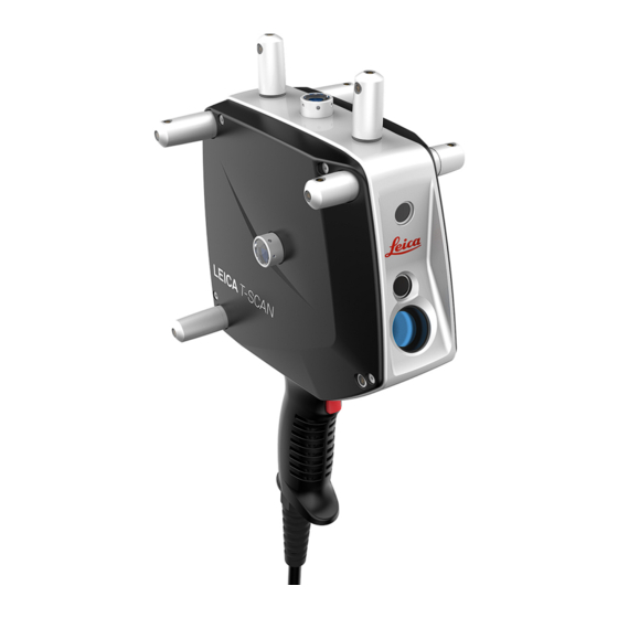
System Concept General 007442_002 Component Description T‑Scan sensor Used to measure clouds of points. The T‑Scan sensor can be operated as a handheld scanner or can be moun- ted onto a robot or machine. T‑Scan controller Controls scan frequencies. Records and synchronises measurement data. - Page 10 T‑Scan Components T‑Scan Components T‑Scan Sensor Front view Aperture for laser beam (scan line) Aperture for pilot beam Aperture for receiver optics Trigger key 007444_001...
- Page 11 Back view Status LED for T‑Scan con- troller Trigger key (front side) Marker LED Stand-off indicator LED Status LED for Laser Tracker Reflector Speaker 007445_001 T‑Scan Status Information/LEDs T‑Scan indicators Acoustical status information To inform about the current measurement status of the sensor, the T‑Scan can give an acoustical status information.
- Page 12 T‑Scan Components Laser Tracker beam locked on and ready to measure • • Measurement completed 6DOF not available • Laser beam broken • Optical status information The T‑Scan can also give optical information to inform about the status of the sensor and the communication to other system components: Stand-off indicator LED Status LED for T‑Scan controller...
- Page 13 Stand-off indicator The Stand-off indicator LED shows the following status cases: LED Sta- Status information Laser Tracker beam is not locked on or T‑Scan sensor is outside of working range Maximum working distance, stand-off is at far end of working range Mid working distance Minimum working distance, stand-off is at close end of working...
- Page 14 T‑Scan Components Status LED for The status LED for the Laser Tracker shows: Laser Tracker the communication status between T‑Scan sensor and Laser Tracker • the measurement status of the T‑Scan system • Colour Pattern Status information LED OFF No communication between T‑Scan and Laser Tracker.
- Page 15 Colour Pattern Status information LED OFF T‑Scan controller is OFF. No communication between controller and sensor Blinking Power on Yellow Blinking Booting Green Blinking Successfully booted Communication between T‑Scan controller and sensor is okay. Green Static Computer software has connected to T‑Scan con- troller.
- Page 16 T‑Scan Components Front view Power switch 015306_001...
- Page 17 Back view Connector for scanner cable Fuse Power socket for: MPS21 or MPB25 Connector for trigger cable LAN connection to applica- 007452_003 Connector for trigger/probe tion computer cable MPS21, power supply unit LAN connection to Laser MPB25, external Li-Ion bat- Tracker controller tery: 37 V and 8.1 Ah T‑Scan Components...
-
Page 18: Care And Transport
Care and Transport Care and Transport Care and transport Carry the product in its original container or attached to the Measurement • Cart, to protect the product against shock and vibration. • Periodically carry out test measurements and perform the field adjustments indicated in the User Manual, particularly after the product has been drop- ped, stored for long periods or transported. -
Page 19: Technical Data
Technical Data Environmental Temperature specifications Type Operating temperature Storage temperature T‑Scan, Controller +0 °C to +40 °C ˗25 °C to +70 °C (+32 °F to +10 °F) (+77 °F to +158 °F) MPS21 +0 °C to +60 °C ˗40 °C to +85 °C (+32 °F to +140 °F) (˗40 °F to +158 °F) MPB25... - Page 20 Technical Data Elevation Range [m] Range [ft] Storage ˗700 to +21000 ˗2300 to +70000 Protection against water, dust and sand Type Protection T‑Scan IP40 (IEC 60529) T‑Scan Controller IP40 (IEC 60529) MPS21 IP22 (IEC 60529) MPB25 IP54 (IEC 60529) Electrical Power MPS21 AC/DC Adapter Value Input Voltage...
- Page 21 MPS21 AC/DC Adapter Value Max. input AC current (over current protection) MPB25 External Li-Ion Battery Value Output Voltage 37 V DC Capacity 8.1 Ah Max. DC current (over current protection) Technical Data...
-
Page 22: Operation
Operation Operation General The first installation of the product should be done by authorised Leica Geosys- tems personnel. Installation by unauthorised personnel may cause damage and will make the warranty null and void. Step-by-step Setting up and connecting the T‑Scan system components Set up the Absolute Tracker system according to the instruction given in the Absolute Tracker User Manual. - Page 23 Starting the data recording Switch on the Absolute Tracker system, the T‑Scan controller and the application computer. Start the application on the application computer and connect to the T‑Scan system. Initialise the Absolute Tracker. To start data recording, hold down the trigger button on the handle of the T‑Scan sensor.
-
Page 24: Ec Declaration Of Conformity
EC Declaration of Conformity EC Declaration of This corresponds to EN ISO/IEC 17050-1. Conformity We, Leica Geosystems AG, CH-9435 Heerbrugg (Switzerland), declare under our sole responsibility that the product(s) T‑Scan 5, following the provision of Directive(s) 2011/65/EU Restriction of hazardous substances (RoHS) •... - Page 26 820806-1.2.0en Original text Printed in Switzerland © 2017 Leica Geosystems AG, Heerbrugg, Switzerland www.leica-geosystems.com...
Need help?
Do you have a question about the T-Scan 5 and is the answer not in the manual?
Questions and answers