Table of Contents
Advertisement
Quick Links
Instruction and service manual
Repair Instructions
Vacuum pumps
VWZ
VWZ
702
VWZ 1002
VWZ 1202
BE 134
1.4.99
Werner Rietschle
GmbH + Co. KG
Postfach 1260
D-79642 Schopfheim
0 7622 / 3 92-0
Fax 0 7622 / 39 23 00
e-mail: info@rietschle.com
http://www.rietschle.com
Rietschle (UK) Ltd.
Bellingham Way
New Hythe
Kent ME20 6XS
0 1622 / 71 68 16
Fax 0 1622 / 71 51 15
e-mail: info@rietschle.co.uk
http://www.rietschle.co.uk
Advertisement
Table of Contents

Related Manuals for Rietschle VWZ Series


Summary of Contents for Rietschle VWZ Series
- Page 1 D-79642 Schopfheim 0 7622 / 3 92-0 Fax 0 7622 / 39 23 00 e-mail: info@rietschle.com http://www.rietschle.com Rietschle (UK) Ltd. Bellingham Way New Hythe Kent ME20 6XS 0 1622 / 71 68 16 Fax 0 1622 / 71 51 15 e-mail: info@rietschle.co.uk...
-
Page 2: Table Of Contents
Contents Page Instruction and service manual VWZ 102 – VWZ 402 Introduction Application Variations and Construction Variations Construction Data sheets and spare parts lists Accessories Typical Field of Application Method of Operation Pump Pressure Relief Valve Oil Lubrication Shaft Seals Installation Mechanical Installation 5.1.1... -
Page 3: Introduction
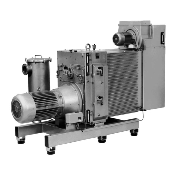
Han- VWZ 702 with closed circulation cooling dling of explodible gases or vapours only on request with our company. Please contact your local Rietschle office for advice. For installation in explosion proof or special areas,motors conforming to the relevant standard must be fitted. -
Page 4: Construction
Vacuum connection 3.2 Construction (fig. 3 and 4) Exhaust connection VWZ pumps are constructed in five main sections, i.e. gear box (Y ), compression Drive stages (S ), oil supply (L to L ), cooling system (R, Y ) and separator Cooling liquid filling cap systems (Z, J ) on the suction side and exhaust side (optional). -
Page 5: Data Sheets And Spare Parts Lists
3.3 Data sheets and spare parts lists see following data sheets: D 134 / DA 134 (USA) External cooling VWZ 702 – VWZ 1202 (14) D 137 / DA 137 (USA) Circulation cooling VWZ 702 – VWZ 1202 (13) see following spare parts lists: E 165/1 Parts for fundamental Units E 165/2... -
Page 6: Method Of Operation
4. Method of operations 4.1 Pump The compressor unit of the VWZ is a fresh oil, once through lubricated, rotary vane type pump. The flow direction is from top to bottom, so that any contamination in the suction stream or condensate is readily discharged. 4.2 Pressure relief valve The spring loaded pressure relief valve is located between the LP and HP stages. -
Page 7: Electrical Installation
5.2 Electrical Installation 5.2.1 General (see data sheets D 131 + D 137) The electrical data can be found on the data plate (N) or the motor data plate. The motors correspond to DIN / VDE 0530 and have IP 54 protection and insulation class B or F. The connection diagram can be found in the terminal box on the motor. Check the electrical data of the motor and the control gear for compatibility with your available supply (voltage, frequency, permissible current etc.). -
Page 8: Normal Operation
6. Normal Operation 6.1 Cooling Liquid 6.1.1 Fresh or External Cooling (fig. 12) For starting-up the pump (VWZ 702 - VWZ 1202 (14)) first the water supply has to be connected to the hose connection point (C). The water jacket (Y ) is filled by pressing the spring loaded priming valve (U ). -
Page 9: Oil Lubrication
6.2 Oil Lubrication (see data sheets D 134 + D 137) Oil metering pump The pumps are despatched with the oil tanks (except fresh oil) filled. However Reduction of oil Increase of oil it is advisable to check the oil levels. Sight glass: Fresh oil (I), LP-bearing (I ), HP-bearing (I ), gearbox (I... -
Page 10: Oil Mist Separator
7.2 Oil Mist Separator (Optional Extra Exhaust Side) The oil mist separator which is mounted directly on the exhaust flange of the vacuum pump is a 2-stage device: Separation: liquid droplets in the condensate collector aerosol in the filter elements The oil mist separators are available in 2 material varia- tions for the chemical and pharmaceutical industries: Stainless steel: 1.4541... -
Page 11: Removal And Reassembly Of Water Jacket
EPAIR NSTRUCTIONS 1. Removal and Re-assembly of Water Jacket (fig. 12, 13 and data sheets D 134 + D 137) • Switch off VWZ and vent to atmospheric pressure • Open plug (U ) or (U • Drain off cooling liquid: - VWZ (14) drain cock (K - VWZ (13) -
Page 12: Changing Coupling Rubbers And Pins
4. Changing Coupling Rubbers and Pins 4.1 On Drive Motor (fig. 22 and 23) • Removal and reassembly of drive (see page 12). • Remove circlips (38) and pull off coupling rubbers (37), replace if necessary. • Remove circlips (87). •... -
Page 13: Reassembly Of Bearings And Seals
5.2 Reassembly of Bearings and Seals (fig. 26) • Before reassembly all parts should be removed from the end cover (25) or (55). Check parts (Pos. 10, 11, 12, 13, 14, 15, 17, 23, 28, 48) and if necessary replace. •... -
Page 14: Changing Blades
6. Changing Blades (fig. 27) • Removal of water jacket and non-drive end B of compressor stage (see page 12 and 13) • Withdraw blades (S ) and examine. • Important! If required, replace blades only in sets. • Insert blades in rotor slots (the bevelled side of the blades have to be at the rotor surface). -
Page 15: Reassembly Of Bearings And Seals
7.2 Re-assembly of Bearings and Seals (see fig. 28 and 29) • Before re-assembly all parts should be removed from the end cover (25) or (55). Check parts (Pos. 10, 11, 12, 13, 14, 15, 16) and if necessary replace. •... -
Page 16: Repairs To Gearbox
8. Repairs to Gearbox 8.1 Removal and Re-assembly of Gearbox (fig. 30 and 31) • Drain oil (see data sheets D 134 + D 137). - Fresh oil at (K) / Bearing oil LP at (K ) and HP at (K - Gearbox oil at (K •... -
Page 17: Changing Bearings, Shaft Seals And Seals
10 Instructions for storing fresh oil lubricated rotary vane vacuum pumps Introduction Start-up of all pumps delivered by Rietschle should be made within 3 months. If this is not possible, please observe the following details, the guarantee given by Rietschle may be invalidated if not followed.
Need help?
Do you have a question about the VWZ Series and is the answer not in the manual?
Questions and answers