Sign In
Upload
Download
Table of Contents
Contents
Add to my manuals
Delete from my manuals
Share
URL of this page:
HTML Link:
Bookmark this page
Add
Manual will be automatically added to "My Manuals"
Print this page
×
Bookmark added
×
Added to my manuals
Manuals
Brands
Dixie Narco Manuals
Vending machines
2145
Operation & service manual
Dixie Narco 2145 Operation & Service Manual
Glass front beverage vender
Hide thumbs
Also See for 2145
:
Technical manual
(79 pages)
1
2
3
Table Of Contents
4
5
6
7
8
9
10
11
12
13
14
15
16
17
18
19
20
21
22
23
24
25
26
27
28
29
30
31
32
33
34
35
36
37
38
39
40
41
42
43
44
45
46
47
48
49
50
51
52
53
54
55
56
57
58
59
60
61
62
63
64
65
66
67
68
69
70
71
72
73
74
75
76
77
78
79
80
81
82
83
84
85
86
87
88
89
90
91
92
93
94
95
96
97
98
page
of
98
Go
/
98
Contents
Table of Contents
Bookmarks
Table of Contents
Table of Contents
General Information
Vender Safety Precautions
Product Identification
Physical Characteristics of 2145 and 2054
Installation & Set-Up
Receiving Inspection
Unpacking the Venders
Electric Power Needed
Coin Changers and Other Accessories
Placing the Vender on Location
Level the Vender
Space the Vender
Product
Service Note
Installation and Setup Instructions
Loading
Loading Change Tubes
MDB and Micromech Units
Cashflow 560 Units
Loading Product
Vending Controller Unit (Vcu)
General Information
Normal Operation Messages
Status Messages
Price Check
Credit
Micromech Unit Operating Mode Menu Items
Mode Menu Item
Service Mode
Test Mode
Setup Mode
Mdb Unit Operating Mode Menu Items
Service Mode
Menu Item
Test Mode
Setup Mode
Cashflow 560 Unit Operating Mode Menu Items
Service Mode
Mode Menu Item
Test Mode
Setup Mode
Initial Programming
Date / Time
Regular Prices
Happy Hour Times
Time
Happy Hour Prices
Price
Not Available Times
Time
Data Collection
Procedure for Downloading
Portable Printer
Laptop Computer
Example Summary Printout
General Maintenance
Power
Cleaning
Figure 1 – Controller Board Connections
Figure 2 – Mdb Controller Connections
Eprom Replacement
Major Component Description
Ac Distribution Box
Refrigeration Unit
Problem Solving Chart
Figure 4 – Ac Distribution Box Schematic
Figure 5 – Ac Distribution Box, J2 Voltages
Figure 6 – System Schematic (Left Side)
Figure 7 – System Schematic (Right Side)
Figure 8 – System Schematic (Right Side; Mdb)
Figure 9 – Compressor Wiring Diagram (2054)
Figure 10 – Compressor Wiring Diagram (2145 – in Line Condenser)
Figure 11 – Compressor Wiring Diagram (2145 – Roll up Condenser)
Figure 12 – Machine Front View
Figure 13 – Cabinet Detail
Figure 14 – Refrigeration Unit – Copeland (2054)
Figure 15 – Refrigeration Unit – Tecumseh (2145 – in Line Condenser)
Figure 16 – Refrigeration Unit – Tecumseh (2145 – Roll up Condenser)
Figure 17 – Service Door (Front)
Figure 18 – Service Door (Back)
Figure 19 – Short Gate Detail
Figure 21 – Tall Gate Detail
Figure 22 – Tall Gate Tray Detail
Figure 23 – Ac Distribution Box, 110 Vac
Figure 24 – Ac Distribution Box, 220Vac
Compatible Currency/Credit Units
Mdb Coin Mechanisms
Mdb Bill Validators
Micro Mech (Mc5000) Coin Mechanisms
Bill Validators Used W/ Micro Mechs (Mc5000)
Micro Mech Card Readers
Peripheral Interface Harness
Advertisement
Quick Links
1
Installation and Setup Instructions
Download this manual
DIXIE-NARCO
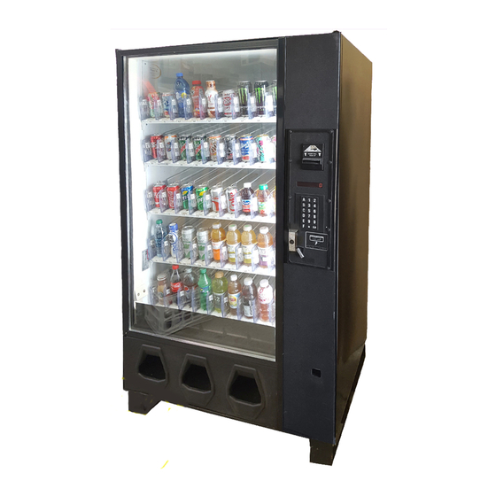
GLASS FRONT BEVERAGE VENDER
Models 2145 & 2054
OPERATION / SERVICE
MANUAL
For Venders Built Prior
To Dixie-Narco Production
0001-8000BW
April 1, 1998
DIXIE-NARCO BLVD.
P.O. DRAWER 719
WILLISTON, SC 29853-0719
(803) 266-5000
Revised August 5, 1998
803,902,770.01
Table of
Contents
Previous
Page
Next
Page
1
2
3
4
5
Advertisement
Table of Contents
Need help?
Do you have a question about the 2145 and is the answer not in the manual?
Ask a question
Questions and answers
Related Manuals for Dixie Narco 2145
Vending machines Dixie Narco 55 Series Technical Manual
Glassfront beverage vender (79 pages)
Vending machines Dixie Narco DN 2145 Technical Manual
Glassfront beverage vender (89 pages)
Vending machines Dixie-Narco 2054 Operation & Service Manual
Glass front beverage vender (98 pages)
Vending machines Dixie-Narco 90 Series Operation Manual
Single price / siid e-model venders (77 pages)
Vending machines Dixie Narco DN 55 Series Technical Manual
Glassfront beverage vender (89 pages)
Vending machines Dixie-Narco SIID Operation And Service Manual
Electronic venders with two button programming (14 pages)
Vending machines Dixie Narco FLEXPAK 3000 Series Programming/Set-Up/Configuration/Troubleshooting/Operation/Parts Manual
(61 pages)
Vending machines Dixie Narco HVV 276E Assembly
Energy star evaporator fan motor sub (6 pages)
Vending machines Dixie Narco 90 Series Installation And Setup Manual
(9 pages)
Vending machines Dixie Narco 90 Series Service Manual
(39 pages)
Vending machines Dixie Narco Pre SRS 90 SP Troubleshooting Manual
(23 pages)
Vending machines Dixie Narco P Series Manual
(81 pages)
Vending machines Dixie Narco P Series Technical Manual
Pepsi-cola high visibility vender (76 pages)
Vending machines Dixie Narco DNCB 168 Parts Service Troubleshooting Manual
Coca-cola marketing machine (85 pages)
Vending machines Dixie Narco P Series Technical Manual
Coca-cola lean marketing vender (83 pages)
Vending machines Dixie Narco DNCB 501T Service Manual
Single price venders (71 pages)
This manual is also suitable for:
2054
Dn 2145
Table of Contents
Save PDF
Print
Rename the bookmark
Delete bookmark?
Delete from my manuals?
Login
Sign In
OR
Sign in with Facebook
Sign in with Google
Upload manual
Upload from disk
Upload from URL


Need help?
Do you have a question about the 2145 and is the answer not in the manual?
Questions and answers