Table of Contents
Advertisement
Available languages
Available languages
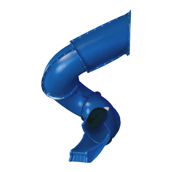
7' Turbo Tube Slide
Note: This accessory is designed to fit a 7' Deck height only.
C A U T I O N
•
Do not climb on the
outside of the slide
• This slide is designed for
home use only, not for
Public Playgrounds
• Product intended for
children ages from 2-10
years old.
WARNING:
!
Assembly by an adult.
PLEASE READ BEFORE BEGINNING ASSEMBLY!!
Please make sure all lumber, hardware and accessory parts are accounted for. If you are missing
DO NOT RETURN
anything, please
To register your product and download unit specific Turbo Tube Slide instructions, visit:
Other benefits include information on product warranties, assembly plan updates, joining our mailing
list for new products and promotions, and providing feedback on products.
IMPORTANT!!
Service Department at the number below.
http://www.swing-n-slide.com
Swing•N•Slide • 1212 Barberry Drive • Janesville, Wisconsin 53545
Visit our web site at: www.swing-n-slide.com or call us at
1-800-888-1232
to the store where purchased. Please call our Customer
Advertisement
Table of Contents

Related Manuals for Swing-N-Slide 7' Turbo Tube Slide


Summary of Contents for Swing-N-Slide 7' Turbo Tube Slide
- Page 1 Other benefits include information on product warranties, assembly plan updates, joining our mailing list for new products and promotions, and providing feedback on products. Swing•N•Slide • 1212 Barberry Drive • Janesville, Wisconsin 53545 Visit our web site at: www.swing-n-slide.com or call us at 1-800-888-1232...
- Page 2 Turbo Tube Slide Dimensions 63-7/16'' 58-11/16'' 34-3/4''...
- Page 3 Proper Placement of Turbo Tube Slide on The Tower Option 3 Swing beam Safety Zone Tower Deck Swing beam Option 2 Swing beam Safety Zone Option 1 NOTE: This diagram is based on a 47-1/2’’ square deck.
- Page 4 Safety Checklist for Swing-N-Slide Play Sets and ccessories Observing the following statements and warnings reduces the likelihood of serious or fatal injury Installation Safety – Have You: Consulted the assembly instructions supplied with your particular model? Noted this accessory is to be used only on Swing•N•Slide approved designs? (Do not alter its design or add/remove components.) Made sure all hardware is tightened securely? (Supplied bolt covers must also be fastened securely.)
- Page 5 Swing-N-Slide® will repair, or at its discretion, replace any part within the stated warranty period which is defective in workmanship or materials. This decision is subject to verification of the defect upon delivery of the defective part to Swing-N-Slide® at 1212 Barberry Drive, Janesville, Wisconsin, 53545. Any part(s) returned to Swing-N- Slide®...
- Page 6 TOOLS REQUIRE CIRCUlAR SAW DRIll 1/2" SOCKET & WRENCH TAPE MEASURE WRENCH SAFETy GlASSES 1/8" DRIll bIT SQUARE PHIllIPS bIT & DUST MASK HARDWARE INClUDED (12) 5/16'' x 1-1/2'' Lag Bolts (95) 5/16'' x 3/4" Hex Head Bolts (214) 5/16'' Flat Washers (2) 5/16'' x 2-3/4'' Bolts (101) 5/16'' loc nuts (4) 5/16'' x 1'' Bolts...
- Page 7 SlIDE COMPONENTS (1) Slide Bracket (1) Entrance Section marked no. 1 (1) Entrance Panel (1) Support Bracket (1) Entrance Section marked no.2 (1) Exit Section marked no. 5 (2) 90 Sections w/flange, marked no. 4 (3) 90 Sections w/o flange, marked no. 3 (1) Slide Base marked no.
- Page 8 ssembly Instructions EntrancE SEction, 90° SEction (2) Fig. 1 and Exit SEction notES: • At least two individuals are needed to assemble the Turbo Tube Slide. • To aid in aligning holes when assembling sections, insert a screwdriver through adjacent holes to maintain hole alignment.
- Page 9 ssembly Instructions Mounting PanEl Fig. 4 1. Position the mounting panel as indicated in (Fig. 4) (The stamped "T" should be at the top). The panel should be placed to the opening so all the bolt holes fully expose a wood surface except those identified with arrows (which should be clear of any wood surface).
- Page 10 ssembly Instructions tubE aSSEMbly Fig. 7 1. Position the 90 section to the entrance section so Rotate seam the seams line up. Rotate the section two holes two holes to to the right (clockwise) and realign with the holes the right (clockwise) of the entrance section (see Fig.
- Page 11 ssembly Instructions tubE aSSEMbly (cont.) Fig. 9 Position the exit section to the previously attached sections so the seams line up. Rotate the section two holes to the left (counterclockwise) and realign with the holes of the entrance section (see Fig. Insert a 3/4"...
- Page 12 ssembly Instructions Mounting SlidE Fig. 11 2-3/4" bolt The help of at least one other individual will be required for mounting the slide. 2-3/4" bolt washer Insert the 2-3/4" bolts through a washer, through previously drilled 3/8" holes in the washer upper rail of the unit (see Fig.
- Page 13 ssembly Instructions SuPPort and brackEt aSSEMbly Fig. 13 1. Position the slide bracket between the slide and activity center (Fig. 13). Remove appropriate bolts from the slide (the fourth and fifth bolts as indicated), Attach bracket to the underside of the seam using the previously removed exit section hardware (Fig.
- Page 14 Instrucciones de Ensamblaje - Instructions d’assemblage ENSAMblAjE DE RESPAlDO y SOPORTE Coloca el soporte del tobogán entre el tobogán y el centro de Fig. 13 actividades (Fig. 13). Quita los pernos adecuados del tobogán (el cuarto y quinto perno, como se indica), asegura el soporte al lado inferior del borde usando los herrajes recién quitados (Fig.
- Page 15 Instrucciones de Ensamblaje - Instructions d’assemblage MONTAjE DEl TObOGáN Fig. 11 perno de 2-3/4 plg Necesitarás la ayuda de al menos una otra persona boulon de 2-3/4 po para montar el tobogán. Inserta los pernos de 2-3/4 plg a través de una arandela perno de 2-3/4 plg arandela, y de los orificios de 3/8 plg taladrados...
- Page 16 Instrucciones de Ensamblaje - Instructions d’assemblage ENSAMBLAJE DEL TUBO Fig. 9 (CONTINUACIÓN) Inserta un perno de 3/4 plg a través de una arandela, a través de las secciones del tobogán y una segunda arandela, y asegúralo con una contratuerca. NOTA: Por el momento, aprieta las contratuercas con la mano solamente.
- Page 17 Instrucciones de Ensamblaje - Instructions d’assemblage ENSAMblAjE DEl TUbO Fig. 7 Coloca la sección de 90º en la sección de entrada de tal manera que los bordes queden alineados. Rota la sección Rota el borde dos dos orificios hacia la derecha (en el sentido de las agujas del orificios hacia la reloj) y vuelve a alinearla con los orificios de la sección de derecha (en sentido...
- Page 18 Instrucciones de Ensamblaje - Instructions d’assemblage PANEl DE MONTAjE Ubica el panel de montaje como se indica en la Fig. 4 (La "T" Fig. 4 estampada debe ir en la parte superior). El panel debe ubicarse en la abertura para que todos los orificios expongan completamente una superficie de madera, excepto aquellos identificados con flechas (que no deben tener cerca ninguna superficie de madera).
- Page 19 Instrucciones de Ensamblaje - Instructions d’assemblage SECCIóN DE ENTRADA, SECCIóN DE 90° (2) y SECCIóN DE SAlIDA Fig. 1 NOTAS: • Hacen falta al menos dos personas para ensamblar el Tobogán de Tubo Turbo. • Para ayudar a alinear los orificios al ensamblar las secciones, inserta un destornillador a través de orificios adyacentes.
- Page 20 COMPONENTES DEL TOBOGÁN COMPOSANTS DU TOBOGGAN 1 Soporte de Tobogán Support du toboggan 1 Sección de Entrada marcada con el núm. 1 Section d’entrée marquée n° 1 1 Panel de Entrada Panneau d’entrée 1 Soporte de Respaldo Support de fixation 1 Sección de Entrada marcada con el núm.
- Page 21 FS 2419 HERRAMIENTAS NECESARIAS OUTILS REQUIS WASHER 8MM LLAVE Y DADOS DE 1/2 PLG TALADRO SIERRA CIRCULAR CINTA MÉTRICA DOUILLE ET CLÉ DE 1/2 PO SCIE CIRCULAIRE PERCEUSE RUBAN À MESURER FS 2422 WASHER FLAT 1/4 ACQ GAFAS DE SEGURIDAD LLAVE BROCA DE ESCUADRA BROCA DE TALADRO DE 1/8 PLG y MASCARA CONTRA El POlVO...
- Page 22 DE POR VID DEL F BRIC NTE Swing-N-Slide® garantiza que sus toboganes termoformados y montañas para escalar estarán libres de defectos de mano de obra y materiales, bajo condiciones y uso normales, durante la vida útil del producto. G R NTÍ...
- Page 23 Cuando el equipo sea retirado de servicio, se debe desarmar y desechar de tal manera que no presente peligros no razonables al momento de desecharlo. ¡Importante! Instrucciones de seguridad adicionales para todos los equipos de juego Swing-N-Slide. Guardar esta hoja de instrucciones en caso de que se requiera contactar al fabricante.
- Page 24 G R NTIE LIMITÉE DU F BRIC NT Swing-N-Slide® Swing-N-Slide® est fière de la qualité et de la durabilité de ses produits. Notre garantie limitée du fabricant donne l'assurance et démontre notre engagement envers la fabrication d'articles pour terrain de jeu résidentiel de qualité.
- Page 25 Lorsque l’équipement est mis hors service, il doit être démonté et conditionné de sorte qu’aucun danger justifié ne sera présent lors de la mise au rebut de l’ensemble. Important! Instructions supplémentaires de sécurité pour tous les centres de jeu Swing-N-Slide. Conserver ce feuillet d’instruction au cas où vous devriez prendre contact avec le fabricant.
- Page 26 Ubicación Correcta del Tobogán de Tubo Turbo en la Torre Placement adéquat du toboggan Turbo Tube sur la tour Opción 3: Option 3 : NO~NON Zona de Seguridad de la Viga del Columpio Zone de sécurité du bras de balançoire Terraza de la Torre Plate-forme de la tour Viga del Columpio...
- Page 27 Dimensiones del Tobogán de Tubo Turbo Dimensions du toboggan Turbo Tube 63-7/16" (1,61 m) 58-11/16" (1,49 m) 34-3/4’’...
- Page 28 à notre liste de diffusion pour les nouveaux produits et promotions et fournir des commentaires sur les produits Swing•N•Slide • 1212 Barberry Drive • Janesville, Wisconsin 53545 Visita nuestro sitio en Internet: www.swing-n-slide.com o llámanos al Veuillez visiter notre site à l’adresse suivante : www.swing-n-slide.com ou appelez-nous au 1-800-888-1232 © PlayCore Inc. 2013...
Need help?
Do you have a question about the 7' Turbo Tube Slide and is the answer not in the manual?
Questions and answers
what is the best way to disassemble the tube slide for disposal