Advertisement
Quick Links
R
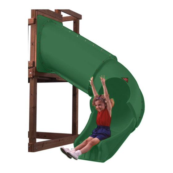
NE 4680-T
TM
Twister Tube
Slide
check out http://www.swing-n-slide.com
for updates to these instructions.
72'' Minimum
Safety Zone
ASSEMBLY INSTRUCTIONS
Swing•N•Slide • 1212 Barberry Drive • Janesville, Wisconsin 53545
Visit our web site at: www.swing-n-slide.com or call us at 1-800-888-1232
Advertisement

Subscribe to Our Youtube Channel
Related Manuals for Swing-N-Slide Twister Tube Slide


Summary of Contents for Swing-N-Slide Twister Tube Slide
- Page 1 NE 4680-T Twister Tube Slide check out http://www.swing-n-slide.com for updates to these instructions. 72'' Minimum Safety Zone ASSEMBLY INSTRUCTIONS Swing•N•Slide • 1212 Barberry Drive • Janesville, Wisconsin 53545 Visit our web site at: www.swing-n-slide.com or call us at 1-800-888-1232...
- Page 2 When the equipment is taken out of service, it must be disassembled and disposed of in such a way that no unreasonable hazards will exist at the time the set is discarded. Important! Additional Safety Instructions for all Swing-N-Slide Playground Equipment. Save this instruction sheet in the event the manufacturer needs to be contacted.
- Page 3 This product is intended for single family home/residential use only and not intended for use in any public setting. Placement in any public setting constitutes a misuse of this product. IMPORTANT! ADDITIONAL REQUIRED SAFETY INSTALLATION INSTRUCTIONS According to ASTM requirements, all kits must be anchored to the ground and, if the unit has a climbing rope, the rope end must be anchored to the ground. If soil conditions permit stakes to be pulled out easily, cementing into ground is necessary.
-
Page 4: Tools Required
(2)-2'' x 4'' x 96'' Note: To match the wood appearance on your playset, make certain to use the precise Wood Stain listed at (1)-2'' x 4'' x 120'' www.swing-n-slide.com LUMBER CUT LIST 47-1/2'' 47-1/2'' (1) 2'' x 4'' x 96''... -
Page 5: Slide Components
SLIDE COMPONENTS (1) Support Bracket (1) Entrance Panel (1) Entrance Section marked no. 1 (1) Entrance Section marked no.2 (1) Exit Section marked no. 5 (1) 90˚ Sections w/o flange, marked no. 3 (1) Slide Base marked no. 6 HARDWARE INCLUDED (12) 1-1/2"... - Page 6 A. ENTRANCE SECTION, AND 90° SECTION NOTES: • At least two individuals are needed to assemble the Twister Tube Slide. • To aid in aligning holes when assembling sections, insert a screwdriver through adjacent holes to maintain hole alignment. Identify each slide section as either (1), (2), (3), (5), or (6) as marked on the lip of each piece.
- Page 7 Twister Tube ssembly Instructions Fig. 2 2-1/2'' 2-1/2'' screw Fig. 2a screws per joint 2-1/8'' B. Slide Barrier Construction 1. Carefully remove (2) 1'' x 4'' Barrier Supports and (8) 1'' x 4'' Barrier Boards from the barrier where you would like to place your slide, making certain you will have a clear 72'' Safety Zone for your slide.
- Page 8 Twister Tube ssembly Instructions Fig. 3 Fig. 3a 2'' deck 1-1/4'' deck screws 2-1/2'' deck screws per joint screws Thru 1'' x 4'' Into 2'' x 4'' 2-1/2'' Gap Between Each Barrier Board 1-1/4'' screw Fig. 3b C. Slide Barrier Cont. 1.
- Page 9 Twister Tube ssembly Instructions Fig. 4 Fig. 4a D. Slide Support and Entry Fig. 4b 1" bolt 1" perno boulon de 1 po 1. Align the mounting panel to the previously assembled entrance section (Fig. 4). Attach the mounting panel to the entrance section at the hole locations indicated in (Fig.
- Page 10 Twister Tube ssembly Instructions Fig. 5 Note: Two holes should be on the right side of the seam formed by pieces 1 & 2 of Section A. Entrance Section Exit Section Fig. 5a Loc Nut Note: One hole of exit section should be exposed.
- Page 11 1-1/2'' 1-1/2'' Lag Bolt Lag Bolt 2-1/2'' 2-1/2'' 1-1/2'' Lag Bolt Lag Bolt Lag Bolt 1-1/2'' Lag Bolt 2-1/2'' Lag Bolt F. Secure Slide In Place 1. Attach Twister Tube Slide to your prepared entrance as shown in (Fig. 6).
- Page 12 Twister Tube ssembly Instructions G. SUPPORT AND BRACKET Fig. 7 FIGURE 14 ASSEMBLY 2" x 4" x 11-1/2" 2" x 4" x 8-1/4" 1. Assemble the support base as shown in (FIG. 7). 2" x 4" x 18" 2" x 4" x 18" 2.
- Page 13 Twister Tube ssembly Instructions Fig. 8 2'' x 4'' x 17'' 1-1/4'' screws H. Slide Installation. 1. Position slide to determine proper location for stake. 2. Drive wood stake into ground leaving 2'' exposed. 3. Secure the slide bottom to the stake using (2) 1-1/4'' deck screws. (Fig. 8).
- Page 14 Twister Tube ssembly Instructions...
- Page 15 Twister Tube ssembly Instructions...
- Page 16 Questions???... Call our Customer Service Department at 1-800-888-1232 © PlayCore Inc. 2009 Printed In USA LA 6066...
Need help?
Do you have a question about the Twister Tube Slide and is the answer not in the manual?
Questions and answers