Table of Contents
Advertisement
Quick Links
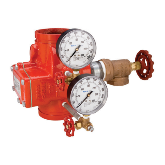
Model CV-1FR Grooved-End
Riser Check Valves
2 Inch to 12 Inch (DN50 to DN300)
General
Description
The TYCO Model CV-1FR Grooved-
End Riser Check Valve is a compact
and rugged swing-type unit that allows
water flow in one direction and pre-
vents flow in the opposite direction.
A resilient elastomer seal facing on
the spring-loaded clapper ensures a
leak-tight seal and non-sticking opera-
tion. The Model CV-1FR Riser Check
Valves are designed to minimize water
hammer caused by flow reversal.
The Model CV-1FR Riser Check Valve
is furnished with grooved ends and
can be installed using GRINNELL
Grooved Couplings or GRINNELL
Figure 71 Flange Adapters. The Model
CV-1FR Riser Check Valves have been
designed with a removable cover for
ease of field maintenance. These valves
can be installed horizontally (with cover
in the upward position) or vertically with
the flow in the upward direction. Refer
to Figure 6.
To facilitate their use in wet-type auto-
matic sprinkler system risers, the
Model CV-1FR Riser Check Valves are
provided with threaded outlets for pres-
sure gauges and a drain connection.
They provide a more compact and eco-
nomical alternative to an alarm check
valve where a water motor alarm is not
required. Provisions must be made for
a local alarm using an approved flow
switch (not included).
The Model CV-1FR Riser Check Valve
is also Listed for use in conjunction
with the TYCO DV-5 Deluge Valve in
Preaction Systems under air pressure
without the use of prime water.
The Model CV-1FR Riser Check Valves
are a redesign for the Central Figure
590FR and GRINNELL Figure 590FR.
IMPORTANT
Refer to Technical Data Sheet
TFP2300 for warnings pertaining to
regulatory and health information.
Page 1 of 4
NOTICE
The Model CV-1FR Riser Check Valve
described herein must be installed
and maintained in compliance with
this document and with the applicable
standards of the NATIONAL FIRE PRO-
TECTION ASSOCIATION, in addition to
the standards of any authorities having
jurisdiction. Failure to do so may impair
the performance of this device.
Never remove any piping component
nor correct or modify any piping defi-
ciencies without first de-pressurizing
and draining the system. Failure to do
so may result in serious personal injury,
property damage, and/or impaired
device performance.
The owner is responsible for maintain-
ing their fire protection system and
devices in proper operating condition.
Contact the installing contractor or
manufacturer with any questions.
Technical
Data
Approvals
UL, C-UL Listed
FM Approved
Sizes
2 in. to 12 in. (DN50 to DN300)
Maximum Working Pressure
300 psi (20,7 bar)
Valve Assembly Finish
Red, non-lead paint
AUGUST 2018
Worldwide
www.tyco-fire.com
Contacts
Installation
The Model CV-1FR Riser Check Valves
are to be installed in accordance with
this section:
1. The arrow cast on the Body must
point in the direction of the flow.
2. Valves installed vertically must
be positioned with the flow in the
upward direction.
3. Valves installed horizontally must be
positioned with the Cover facing up.
Refer to Figure 6.
4. Grooved-end pipe couplings used
with the Model CV-1FR Riser Check
Valve must be installed in accordance
with manufacturer's instructions.
NOTE: Valves should be installed a
reasonable distance downstream from
pumps, elbows, expanders, reducers,
or other similar devices to extend the
valve life. Standard piping practices
call for a minimum of five times the pipe
diameter for general use.
TFP950
Advertisement
Table of Contents

Related Manuals for Tyco CV-1FR


Summary of Contents for Tyco CV-1FR
- Page 1 Model CV-1FR Grooved-End Riser Check Valves 2 Inch to 12 Inch (DN50 to DN300) General NOTICE The Model CV-1FR Riser Check Valve Description described herein must be installed and maintained in compliance with The TYCO Model CV-1FR Grooved- this document and with the applicable...
- Page 2 DN250 (273,1) (457,2) (314,5) (218,9) (162,8) (190,5) (273,1) (85,9) (178) (49,4) 12.750 21.0 14.28 9.93 7.27 7.62 10.00 3.13 151.0 DN300 (323,9) (533,4) (362,7) (252,2) (184,7) (193,5) (254,0) (79,5) (178) (68,0) FIGURE 1 MODEL CV-1FR RISER CHECK VALVES NOMINAL DIMENSIONS...
- Page 3 Steel (DN50-200) Clapper Retaining Stainless 10˝ - 12˝ Ductile Iron Disc Steel (DN250-300) FIGURE 2 MODEL CV-1FR RISER CHECK VALVES ASSEMBLY FLOW RATE IN LITRES PER MINUTE (LPM) (1 GPM = 3,785 LPM) 1000 2000 3000 5000 7000 10000 20000...
- Page 4 DN200 (219,1) (355,6) (241,7) (138,7) (350,7) 10.750 18.00 10.41 7.50 14.70 DN250 (273,1) (457,2) (264,3) (190,5) (373,3) 21.00 12.750 11.27 7.62 15.56 DN300 (323,9) (533,4) (286,1) (193,5) (395,2) FIGURE 4 MODEL CV-1FR RISER CHECK VALVE WITH TRIM COMPONENTS NOMINAL DIMENSIONS...
- Page 5 1/4" x 5" Nipple ..2" x 3" Nipple ..FIGURE 5 MODEL CV-1FR RISER CHECK VALVES TRIM PARTS LIST COVER OUTLET INLET OUTLET...
- Page 6 (P/N). and advise those responsible for moni- toring proprietary and/or central station Model CV-1FR Check Valves alarms. Specify: Size and P/N (below): The owner is responsible for the 2 in. (DN50) ... . . P/N 59-590-1-020 inspection, testing, and maintenance of 2-1/2 in.
Need help?
Do you have a question about the CV-1FR and is the answer not in the manual?
Questions and answers