
Related Manuals for Rosemount 248


Summary of Contents for Rosemount 248
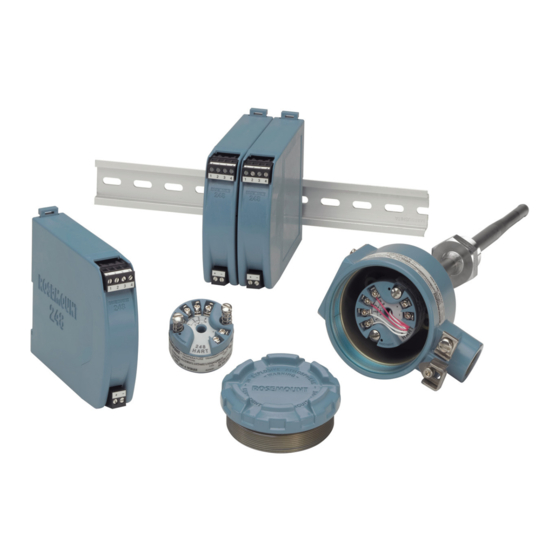
- Page 1 Reference Manual 00809-0100-4825, Rev BB August 2005 Rosemount 248 Transmitter and Temperature Monitoring Assembly www.rosemount.com...
- Page 3 Using non-nuclear qualified products in applications that require nuclear-qualified hardware or products may cause inaccurate readings. For information on Rosemount nuclear-qualified products, contact a Emerson Process Management Sales Representative. Rosemount 248 Temperature Monitoring Assembly may be protected by one or more U.S. Patents pending. Other foreign patents pending. www.rosemount.com...
-
Page 5: Table Of Contents
Reference Manual 00809-0100-4825, Rev BB Rosemount 248 August 2005 Table of Contents SECTION 1 Safety Messages ......... 1-1 Warnings . - Page 6 Reference Manual 00809-0100-4825, Rev BB Rosemount 248 August 2005 SECTION 4 Safety Messages ......... 4-1 Warnings .
-
Page 7: Safety Messages
Reference Manual 00809-0100-4825, Rev BB Rosemount 248 August 2005 Section 1 Introduction Safety Messages ....... . . page 1-1 Overview . -
Page 8: Overview
Refer to the following literature for additional connection heads, sensors, and thermowells that may not be available in the Rosemount 248 model structure: • Temperature Sensors and Assemblies Product Data Sheet, Volume 1 (document number 00813-0100-2654) •... -
Page 9: Considerations
Electrical temperature sensors such as RTDs and thermocouples produce low-level signals proportional to their sensed temperature. The Rosemount 248 converts the low-level sensor signal to a standard 4–20 mA dc signal that is relatively insensitive to lead length and electrical noise. This current signal is then transmitted to the control room via two wires. -
Page 10: Return Of Materials
Reference Manual 00809-0100-4825, Rev BB Rosemount 248 August 2005 Figure 1-1. Rosemount 248 Transmitter Connection Head Temperature Rise vs. Extension Length 150 175 200 Extension Length (mm) Example The transmitter specification limit is 85 °C. If the ambient temperature is 55 °C and the process temperature to be measured is 800 °C, the maximum... -
Page 11: Safety Messages
Reference Manual 00809-0100-4825, Rev BB Rosemount 248 August 2005 Section 2 Installation Safety Messages ....... . . page 2-1 Mounting . - Page 12 Reference Manual 00809-0100-4825, Rev BB Rosemount 248 August 2005 Figure 2-1. Installation Flowchart Bench START Calibration? HERE FIELD INSTALL BASIC SETUP Mount Transmitter Set Sensor Type Wire Transmitter Set Number of Wires Power Transmitter Set Units FINISHED Set Range Values...
-
Page 13: Mounting
MOUNTING Mount the transmitter at a high point in the conduit run to prevent moisture from draining into the transmitter housing. The Rosemount 248R installs directly to a wall or to a DIN rail. The Rosemount 248H installs • In a connection head or universal head mounted directly on a sensor assembly •... -
Page 14: Installation
Rosemount 248 August 2005 INSTALLATION The Rosemount 248 can be ordered assembled to a sensor and thermowell or as a stand-alone unit. If ordered without the sensor assembly, use the following guidelines when installing the transmitter with an integral sensor assembly. -
Page 15: Typical North And South American Installation
Reference Manual 00809-0100-4825, Rev BB Rosemount 248 August 2005 Typical North and South Head Mount Transmitter with Threaded Sensor American Installation Attach the thermowell to the pipe or process container wall. Install and tighten thermowells before applying process pressure. Attach necessary extension nipples and adapters to the thermowell. - Page 16 Reference Manual 00809-0100-4825, Rev BB Rosemount 248 August 2005 Rail Mount Transmitter with Integral Mount Sensor The least complicated assembly uses: • an integral mount sensor with terminal block • an integral DIN style connection head • a standard extension •...
- Page 17 • a threaded thermowell Refer to Volume 1 of the Rosemount Sensors Product Data Sheet (document number 00813-0100-2654) for complete sensor and mounting accessory information. To complete the assembly, follow the procedure described below.
-
Page 18: Multichannel Installations
Reference Manual 00809-0100-4825, Rev BB Rosemount 248 August 2005 MULTICHANNEL Several transmitters can be connected to a single master power supply, as shown in Figure 2-5. In this case, the system may be grounded only at the INSTALLATIONS negative power supply terminal. In multichannel installations where several... -
Page 19: Sensor Connections
250 and 1100 ohms load for communications. Sensor Connections The Rosemount 248 is compatible with a number of RTD and thermocouple sensor types. Figure 2-7 shows the correct input connections to the sensor terminals on the transmitter. To ensure a proper sensor connection, anchor the sensor lead wires into the appropriate compression terminals and tighten the screws. - Page 20 Reference Manual 00809-0100-4825, Rev BB Rosemount 248 August 2005 Figure 2-7. Sensor Wiring Diagrams Rosemount 248 Sensor Connections Diagram 2 3 4 1 2 3 4 1 2 3 4 1 2 3 4 2-wire 3-wire* 4-wire RTD and mV RTD and * Emerson Process Management provides 4-wire sensors for all single element RTDs.
-
Page 21: Power Supply
Reference Manual 00809-0100-4825, Rev BB Rosemount 248 August 2005 Examples of Approximate Lead Wire Resistance Effect Calculations Given: Total cable length: 150 m 0.5 Ω Imbalance of the lead wires at 20 °C: 0.025 Ω/m °C Resistance/length (18 AWG Cu): 0.039 Ω/Ω... -
Page 22: Surges/Transients
To protect against high-energy transients, install the transmitter into a suitable connection head with the Rosemount 470 Transient Protector. Refer to the Rosemount 470 Transient Protector Product Data Sheet (document number 00813-0100-4191) for more information. - Page 23 Reference Manual 00809-0100-4825, Rev BB Rosemount 248 August 2005 Option 1: Connect sensor wiring shield to the transmitter housing (only if the housing is grounded). Ensure the sensor shield is electrically isolated from surrounding fixtures that may be grounded. Ground signal wiring shield at the power supply end.
- Page 24 Reference Manual 00809-0100-4825, Rev BB Rosemount 248 August 2005 Grounded Thermocouple Inputs Option 4 Ground sensor wiring shield at the sensor. Ensure that the sensor wiring and signal wiring shields are electrically isolated from the transmitter housing. Do not connect the signal wiring shield to the sensor wiring shield.
-
Page 25: Safety Messages
Reference Manual 00809-0100-4825, Rev BB Rosemount 248 August 2005 Section 3 Configuration Safety Messages ....... . . page 3-1 Commissioning . -
Page 26: Commissioning
August 2005 COMMISSIONING The Rosemount 248 must be configured for certain basic variables to operate. In many cases, all of these variables are pre-configured at the factory. Configuration may be required if the transmitter is not configured or if the configuration variables need revision. -
Page 27: Hart Menu Tree
4. Intermit Detect 3. Dev Outputs Review 5. Intermit Thresh 4. Device Information 4. REVIEW 5. Measurement Filtering The review menu lists all of the information stored in the Rosemount 248. This includes device information, measuring element, output configuration, and software... -
Page 28: Fast Key Sequence
Reference Manual 00809-0100-4825, Rev BB Rosemount 248 August 2005 Fast Key Sequence Table 3-1 lists the fast key sequences for common transmitter functions. Table 3-1. Rosemount 248 Fast Key Sequence Function Fast Keys Function Fast Key Active Calibrator 1, 2, 2, 1, 3... -
Page 29: Review Configuration Data
Reference Manual 00809-0100-4825, Rev BB Rosemount 248 August 2005 Review Configuration Before operating the Rosemount 248 in an actual installation, review all of the factory-set configuration data to ensure that it reflects the current application. Data Review Fast Key Sequence... - Page 30 Reference Manual 00809-0100-4825, Rev BB Rosemount 248 August 2005 Set Output Units Fast Key Sequence 1, 3, 2, 1, 2, 2 The Set Output Unit command sets the desired primary variable units. Set the transmitter output to one of the following engineering units: •...
- Page 31 To utilize this feature perform the following steps: Measure the lead wire resistance of both RTD leads after installing the 2-wire RTD and the Rosemount 248. From the HOME screen, select 1 Device Setup, 3 Configuration, 2 Sensor Configuration, 1 Sensor 1, 2 Snsr 1 Setup, and 1 2-Wire Offset.
-
Page 32: Information Variables
Reference Manual 00809-0100-4825, Rev BB Rosemount 248 August 2005 Information Variables Access the transmitter information variables on-line using the HART Communicator or other suitable communications device. The following is a list of transmitter information variables. These variables include device identifiers, factory-set configuration variables, and other information. -
Page 33: Diagnostics And Service
Reference Manual 00809-0100-4825, Rev BB Rosemount 248 August 2005 Diagnostics and Service Test Device Fast Key Sequence 1, 2, 1 The Test Device command initiates a more extensive diagnostics routine than that performed continuously by the transmitter. The Test Device menu lists the following options: •... - Page 34 From the HOME screen select 1 Device Setup, 2 Diag/Service, 3 Write Protect. Select Enable WP. NOTE To disable write protect on the Rosemount 248, repeat the procedure, replacing Enable WP with Disable WP. HART Output Fast Key Sequence 1, 3, 3, 3 The HART Output command allows the user to make changes to the multidrop address, initiate burst mode, or make changes to the burst options.
- Page 35 Reference Manual 00809-0100-4825, Rev BB Rosemount 248 August 2005 Alarm and Saturation Fast Key Sequence 1, 3, 3, 2 The Alarm/Saturation command allows the alarm settings (Hi or Low) and saturation values to be viewed and changed. To change the alarm values and saturation values, select the value to be changed, either 2 Low Alarm, 3 High Alarm, 4 Low Sat., or 5 High Sat.
- Page 36 True open sensor conditions will cause the transmitter to go into alarm. The threshold value of the Rosemount 248 should be set at a level that allows the normal range of process temperature fluctuations; too high and the algorithm will not be able to filter out intermittent conditions;...
- Page 37 If the additional verification shows that the open sensor condition is not valid, the transmitter will not go into alarm. For users of the Rosemount 248 that desire a more immediate open sensor detection, the Open Sensor Holdoff option can be changed to a fast setting.
-
Page 38: Multidrop Communication
NOTE Rosemount 248 transmitters are set to address 0 at the factory, allowing them to operate in the standard point-to-point manner with a 4–20 mA output signal. To activate multidrop communication, the transmitter address must be changed to a number between 1 and 15. -
Page 39: Safety Messages
Reference Manual 00809-0100-4825, Rev BB Rosemount 248 August 2005 Section 4 Operation and Maintenance Safety Messages ....... . . page 4-1 Calibration . -
Page 40: Calibration
In operation, the transmitter uses this information to produce a process variable output, in engineering units, dependent on the sensor input. Calibration of the Rosemount 248 may include the following procedures: • Sensor Input Trim: digitally alter the transmitter’s interpretation of the input signal •... - Page 41 Rosemount 248 August 2005 Use the following procedure to perform a sensor trim with a Rosemount 248. Connect the calibration device or sensor to the transmitter. Refer to Figure 2-6 on page 2-9 or inside of the transmitter terminal side cover for sensor wiring diagrams.
-
Page 42: Hardware
Do not remove the thermowell while in operation Select any standard, off-the-shelf sensor for use with a Rosemount 248, or consult the factory for a replacement special sensor and transmitter combination. -
Page 43: Diagnostic Messages
Table 4-1 to verify that transmitter hardware and process connections are in good working order. Under each of four major symptoms, specific suggestions are offered for solving the problem. Table 4-1. Rosemount 248 Troubleshooting Chart Symptom Potential Source Corrective Action... -
Page 44: 375 Field Communicator
Reference Manual 00809-0100-4825, Rev BB Rosemount 248 August 2005 375 Field Communicator Table 4-2 provides a guide to diagnostic messages used by the 375 Field Communicator. Variable parameters within the text of a message are indicated with the notation <variable parameter>. Reference to the name of another message is identified by the notation [another message]. - Page 45 Reference Manual 00809-0100-4825, Rev BB Rosemount 248 August 2005 Message Description Overwrite existing configuration memory Requests permission to overwrite existing configuration either by a device-to-memory transfer or by an offline configuration. User answers using the softkeys. Press OK. Press the OK softkey. This message usually appears after an error message from the application or as a result of HART communications.
- Page 46 Reference Manual 00809-0100-4825, Rev BB Rosemount 248 August 2005...
-
Page 47: Transmitter Specifications
Humidity Limits 0–99% relative humidity, non-condensing NAMUR Recommendations The Rosemount 248 meets the following NAMUR recommendations: • NE 21 – Electromagnetic compatibility (EMC) for Process and Laboratory Apparatus • NE 43 – Standard of the signal level breakdown information of digital transmitters •... - Page 48 Rosemount 248 August 2005 Transient Protection The Rosemount 470 prevents damage from transients induced by lightning, welding, heavy electrical equipment, or switch gears. Refer to the Rosemount 470 Product Data Sheet (document number 00813-0100-4191) for more information. Temperature Limits Operating Limit •...
-
Page 49: Physical Specifications
• O-Ring Seal: Rubber Mounting The Rosemount 248R attaches directly to a wall or a DIN rail. The Rosemount 248H installs in a connection head or universal head mounted directly on a sensor assembly or apart from a sensor assembly using a universal head. - Page 50 1 2 3 4 2-wire 3-wire* 4-wire RTD and and mV * Rosemount Inc. provides 4-wire sensors for all single element RTDs. You can use these RTDs in 3-wire configurations by leaving the unneeded leads disconnected and insulated with electrical tape.
- Page 51 The accuracy and ambient temperature effect is the greater of the fixed and percent of span values (see example below). Table A-2. Rosemount 248 Transmitter Input Options, Accuracy, and Ambient Temperature Effects Temperature Effects per 1.0 °C (1.8 °C) Sensor...
-
Page 52: Sensor Specifications
Table A-6 on page A-12 IEC 584 Construction Rosemount DIN plate and -in. adapter style thermocouples are manufactured from selected materials to meet IEC 584 Tolerance Class 1. The junction of these wires is laser-welded to form a pure joint, maintaining circuit integrity and ensuring highest accuracy. -
Page 53: Rtds
Reference Manual 00809-0100-4825, Rev BB Rosemount 248 August 2005 RTDs Sensor Type 100 ohm RTD at 0 °C, α = 0.00385 ohms/ohm/°C. Accuracy Meets IEC 751 Class B tolerances Temperature Range –50 to 450 °C (–58 to 842 °F) Self Heating 0.15 °K/mW when measured per method defined in DIN EN 60751:1996 or 16... -
Page 54: Dimensional Drawings
Reference Manual 00809-0100-4825, Rev BB Rosemount 248 August 2005 DIMENSIONAL DRAWINGS 248R Railmount Transmitter 248H Headmount Transmitter (enlarged) 95.25 (3.75) 33 (1.3) 44 (1.7) 25.9 (1.02) 123.5 (4.86) 48.77 12.9 (0.51) (1.92) 24.5 (0.97) Dimensions are in millimeters (inches) Enclosures... - Page 55 Reference Manual 00809-0100-4825, Rev BB Rosemount 248 August 2005 Examples of 248 Transmitter and Sensor Assemblies with Thermowells Tubular Thermowell and Barstock Thermowell and Barstock Thermowell, Nipple-Union Extension, DIN Plate Style Sensor DIN Plate Style Sensor -in. NPT Spring Loaded Sensor...
-
Page 56: Ordering Information
Reference Manual 00809-0100-4825, Rev BB Rosemount 248 August 2005 ORDERING INFORMATION Table A-5. Rosemount 248 Transmitter with or without DIN Plate Style Sensor and Tubular Thermowells (millimeters) Product Description 248H Smart DIN B Head Mount Temperature Transmitter Code Output Protocol... - Page 57 Typical Model Number: 248H A E1 A 1 ZR N050 G22 U160 Q4 (1) The Rosemount 248H with CENELEC Type n Component Approval is not approved as a stand alone unit. Additional system certification is required. Transmitters must be installed such that it is protected to at least the requirements of IP54.
- Page 58 Reference Manual 00809-0100-4825, Rev BB Rosemount 248 August 2005 Table A-6. Rosemount 248 Transmitter with or without DIN Plate or -in. Adapter Style Sensor and Barstock Thermowells (millimeters) Model Product Description 248H Smart DIN B Head Mount Temperature Transmitter Code...
- Page 59 Typical Model Number: 248H A I1 A 1 DR N080 T08 U250 CN (1) The Rosemount 248H with CENELEC Type n Component Approval is not approved as a stand alone unit. Additional system certification is required. Transmitters must be installed such that it is protected to at least the requirements of IP54.
- Page 60 Reference Manual 00809-0100-4825, Rev BB Rosemount 248 August 2005 Table A-7. Rosemount 248 Transmitter with or without -in. NPT Spring Loaded Sensor and Barstock Thermowells (inches) Model Product Description 248H Smart DIN B Head Mount Temperature Transmitter Code Output Protocol...
- Page 61 Typical Model Number: 248H A K5 U 2 UR N003 T25 U004 F6 (1) The Rosemount 248H with CENELEC Type n Component Approval is not approved as a stand alone unit. Additional system certification is required. Transmitters must be installed such that it is protected to at least the requirements of IP54.
- Page 62 Aluminum Alloy BUZ Head – M20 Conduit Entry and NPT Instrument Entry 00644-4196-0021 External Ground Screw Assembly Kit 00644-4431-0001 Kit, Hardware for Mounting a Rosemount 248 to a DIN Rail (see left picture-top hat rail, symmetric) 00248-1601-0001 Rail Clip Standard Cover for Universal or Rosemount Connection Heads 03031-0292-0001...
- Page 63 Reference Manual 00809-0100-4825, Rev BB Rosemount 248 August 2005 When a transmitter is ordered alone, the transmitter will be shipped as follows (unless specified): Sensor Type RTD, Pt 100 (α=0.00385, 4-wire) 4 mA Value 0 °C 20 mA Value 100 °C...
- Page 64 Reference Manual 00809-0100-4825, Rev BB Rosemount 248 August 2005 A-18...
-
Page 65: Hazardous Locations Certifications
Canadian Standards Association (CSA) Approvals CSA Intrinsically Safe and Class I, Division 2 Intrinsically Safe for Class I, Division 1, Groups A, B, C, and D when installed in accordance with Rosemount drawing 00248-1056. Temperature Codes: T5 (T = –50 to 60 °C) T6 (T = –50 to 40 °C) -
Page 66: European Approvals (1
Combination of I6 and Explosion-Proof for Class I, Division 1, Groups B, C, and D; Class II, Division 1, Groups E, F, and G; Class III, Division 1 hazardous locations, when installed in accordance with Rosemount drawing 00644-1059. Suitable for Class I, Division 2, Groups A,B, C, and D. -
Page 67: Australian Approvals
The installation guidelines presented by the drawings must be followed in order to maintain certified ratings for installed transmitters. DRAWINGS Rosemount Drawing 00248-1055, Rev AD, 2 Sheets Factory Mutual Intrinsic Safety and Non-Incendive Installation Drawing Rosemount Drawing 00644-1049, Rev AD, 1 Sheet... - Page 68 Reference Manual 00809-0100-4825, Rev BB Rosemount 248 August 2005 Figure B-1. FM Intrinsic Safety and Non-Incendive Installation Drawing 00248-1055, Rev. AD. Sheet 1 of 2...
- Page 69 Reference Manual 00809-0100-4825, Rev BB Rosemount 248 August 2005 Figure B-2. FM Intrinsic Safety and Non-Incendive Installation Drawing 00248-1055, Rev. AD. Sheet 2 of 2...
- Page 70 Reference Manual 00809-0100-4825, Rev BB Rosemount 248 August 2005 Figure B-3. Factory Mutual (FM) Explosion-Proof Installation Drawing 00644-1049, Rev. AD...
- Page 71 Reference Manual 00809-0100-4825, Rev BB Rosemount 248 August 2005 Figure B-4. CSA I Explosion-Proof and Non-Incendive Installation Drawing 00248-1056, Rev. AB.
- Page 72 Reference Manual 00809-0100-4825, Rev BB Rosemount 248 August 2005 Figure B-5. CSA Explosion-Proof Installation Drawing 00644-1059, Rev. AE.
- Page 73 Reference Manual 00809-0100-4825, Rev BB Rosemount 248 August 2005 Figure B-6. IECEx Intrinsic Safety Installation Drawing 00248-1057, Rev. AD...
- Page 74 Reference Manual 00809-0100-4825, Rev BB Rosemount 248 August 2005 B-10...
- Page 75 Reference Manual 00809-0100-4825, Rev BB Rosemount 248 August 2005 Index ... . 3-6 ..B-1 Numerics PV Damping Hazardous Certifications . 3-5 Review Configuration Data Hazardous Locations Certifications 375 Field Communicator .
- Page 76 Reference Manual 00809-0100-4825, Rev BB Rosemount 248 August 2005 ... A-7 Accuracy ... 1-4 Return of Materials ..A-7 Immersion Error .
- Page 77 Reference Manual 00809-0100-4825, Rev BB Rosemount 248 August 2005 NOTES...
- Page 78 Reference Manual 00809-0100-4825, Rev BB Rosemount 248 August 2005 NOTES...
- Page 79 Reference Manual 00809-0100-4825, Rev BB Rosemount 248 August 2005 NOTES...
- Page 80 00809-0100-4825, Rev BB August 2005 Rosemount and the Rosemount logotype are registered trademarks of Rosemount Inc. PlantWeb is a registered trademark of one of the Emerson Process Management group of companies. HART is a registered trademark of the HART Communication Foundation.
Need help?
Do you have a question about the 248 and is the answer not in the manual?
Questions and answers