Advertisement
Quick Links
Advertisement

Subscribe to Our Youtube Channel
Related Manuals for Eclipse AH-MA Series


Summary of Contents for Eclipse AH-MA Series
- Page 1 Design Guide No. 160, 8/1/05 AirHeat Burners AH-MA Series Version 2...
- Page 2 W RR NTY or otherwise, is limited to the furnishing of such replacement parts and Eclipse will not be liable for any other injury, loss, damage or expenses, whether direct or consequential, including but not limited to loss of use, income of or damage to material arising in connection with the sale, installation, use of, inability to use or the repair or replacement of Eclipse’...
- Page 3 Price Sheet No. 160 Used to order burners. LAT D PUBLICATIONS EFE-825 (Combustion Engineering Guide) Eclipse Bulletins & Instruction Manuals: 818, 820, 826, 832, 852, 854, 856 clipse AH-MA Air Heat Burner v2, Design Guide 160, 8/1/05...
- Page 4 Do not deviate from any instructions or application limits in this manual without written consent from Eclipse Combustion. If you do not understand any part of the information in this manual, do not continue. Contact your Eclipse sales office or Eclipse Combustion. CUMENT There are several special symbols in this document.
- Page 5 able of Contents bout this manual Table of Contents Introduction Product Description Safety Introduction Safety Capabilities Operator T raining Replacement Parts System Design Design Burner Design Step 1a: Calculating Maximum Input Required Step 1b: Choosing Design Heat Input at High Fire Step 1c: Determining the Length of Burner Needed Step 1d: Calculating Minimum Input Required Step 1e: Layout of the Burner Sections...
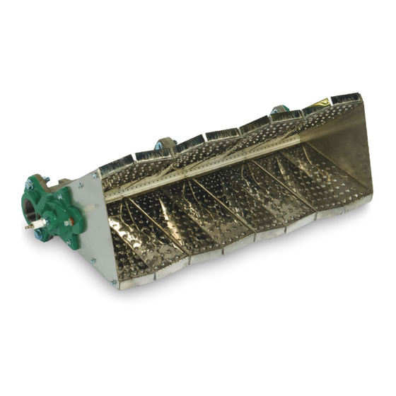
- Page 6 ntroduction clipse AH-MA v2.10 Air Heat burners produce a uniform, odorless, ODUCT and smokeless flame ideal for heating fresh air in make-up and process DESC IPTION air heating applications. The AH-MA design provides stable operation over a wide range of velocities, inputs, and fuels. AH-MA v2.10 burners are line type burners constructed of cast iron or aluminum burner bodies and diverging stainless steel air wings.
- Page 7 Read this entire manual before you attempt to start the system. If you do not understand any part of the information in this manual, then contact your Eclipse representative or Eclipse Combustion before you continue. clipse AH-MA Air Heat Burner v2, Design Guide 160, 8/1/05...
- Page 8 Regular retraining must be scheduled to maintain a high degree of proficiency. PLAC M NT ARTS Order replacement parts from Eclipse only. Any customer supplied valves or switches should carry UL, FM, CSA, CGA and/or CE approval where applicable.
- Page 9 ystem Design esign structure SIGN esigning a burner system is a straight-forward exercise of combining modules that add up to a reliable and safe system. The design process is divided into the following steps: Burner design calculating the maximum input requirements choosing design heat input at high fire determining the length of burner needed calculating the minimum input requirements...
- Page 10 This is an approximation based on the gross heating value of the fuel. For more accurate heat balance calculations, refer to the Eclipse ombustion Engineering Guide (EFE-825). hoosing design heat input at high fire ee Data heet No. 160 for the following: 1) Use the “Operating Range”...
- Page 11 ) From the “Operating Range” chart in Data Sheet No. 160, the maximum heat input at 0.7"w.c. air pressure drop is 800,000 Btu/hr/ft. The flame length from the “Flame Length” chart in Data Sheet No. 160 is 30". Burner length, feet = 6, 40,000 Btu/hr = 7.8 feet; round up to 8 feet. 800,000 Btu/hr/ft 3) Minimum: Btu/hr = 1.3 X 60,000 X 5 = 390,000 Btu/hr.
- Page 12 clipse AH-MA Air Heat Burner v2, Design Guide 160, 8/1/05...
- Page 13 clipse AH-MA Air Heat Burner v2, Design Guide 160, 8/1/05...
- Page 14 clipse AH-MA Air Heat Burner v2, Design Guide 160, 8/1/05...
- Page 15 izing and layout of the gas manifold hoose the gas manifold size to evenly supply gas to each of the sections, using Table 3.3 and Figure 3.2. Gas Pipe Sizing & Layout able 3.3 AXI U ANIFOLD AXI U AIN GAS GAS INPUT PIPE SIZE GAS INPUT...
- Page 16 rofile plate sizing rofile plates are required to ensure sufficient air pressure drop across the burner. An example of profile plate layout is shown in Figure 3.4 on the next page. aution: It is essential that even air flow is delivered to the burner to obtain optimum performance.
- Page 17 igure 3.3 rofile Gap Area vs. Air ressure Gap Burner Air Inlet Temperature @ 70 F Combustion Air Pressure Drop ("w.c.) able 3.4 rofile Gap Area Inlet Air Temperature Correction . 3.4 FROM ORRECT ON ACTOR . (°F) Correction Factor 0.87 0.92 1.00...
- Page 18 igure 3.5 wo-Stage Burner Profile Plates 6" Min. 3" Min. 6" Min. 2" 2" First Second Stage Stage Burner Burner Profile Profile Plate Plate 2" 2" 6" Min. Note: Make all profile gaps equal (shown as “X” above); profile plate width between the burners should be at least 3". Duct Wall Air Flow Air Flow...
- Page 19 ote: To compensate for changes in actual air flow versus calculated, provide adjustable profile plates so that final settings can be made in the field. Figure 3.6 shows an example of an adjustable profile plate design. djustable Profile Plates igure 3.6 AH-MA Burner Adjustable...
- Page 20 tep 2: he simplest control method is fuel modulation at fixed air flow. If Control required turndown is greater than the burner’s capabilities, there Methodology are two options: ir Modulation o lower the minimum input of the burner, the air flow can be decreased as long as the pressure drop across the burner does not go outside of the operating limits given in the “Operating Ranges”...
- Page 21 The pilot fuel is fed into the pilot end casting which is separate from the main fuel. A pilot adjusting valve is required to adjust the pilot gas flow (Eclipse part number 12659 is recommended). The needed pilot capacity is 20,000 Btu/ hr, but the pilot will operate equally well at higher or lower inputs.
- Page 22 Eclipse Combustion recommends the use of flame monitoring control systems which maintain a spark for the entire trial for ignition time when using U.V . scanners.
- Page 23 tep 5: Gas Valve T rain Selection igures 3.9 and 3.10 illustrate gas valve trains for single and staged burner systems respectively. The typical main gas valve train for a staged burner has the same valve layout as a single burner except each burner has an individual sole- noid valve to independently shut down each section.
- Page 24 For details, please contact your local clipse representative or clipse Combustion. ote: Eclipse supports FPA regulations (two shut-off valves) as a minimum standard for main gas “safety shut-off valves. ” clipse AH-MA Air Heat Burner v2, Design Guide 160, 8/1/05...
- Page 25 ppendix NVERSI N etric to English. FACT RS ULTIPLY BY cubic meter (m ) cubic foot (ft ) 35.31 cubic meter/hour (m /h) cubic foot/hour (cfh) 35.31 degrees Celsius (°C) degrees Fahrenheit (°F) (°C x 1.8) + 32 kilogram (kg) pound (lb) 2.205 kilowatt (kW)
- Page 26 Offered By: Power Equipment Company 2011 Williamsburg Road Richmond, Virginia 23231 Phone (804) 236-3800 (804) 236-3882 www.peconet.com...
Need help?
Do you have a question about the AH-MA Series and is the answer not in the manual?
Questions and answers