Table of Contents
Advertisement
Quick Links
INSTALLATION AND MAINTENANCE INSTRUCTIONS
DUCTSD240 Duct Smoke Detector
SPECIFICATIONS
Operating Temperature:
Storage Temperature:
Humidity:
Air Velocity:
DUCTSD240 Footprint Dimensions: Rectangular - 14.38 in L x 4.57 in W x 2.67 in D (37cm L x 11.6cm W x 6.8cm D)
DUCTSD240 Weight:
Electrical
Power supply voltage:
Input capacitance:
Reset Voltage:
Reset Time (with RTS451/RTS151): .03 to 0.3 sec.
Reset Time (by power down):
Power Up Time:
Alarm response time:
Sensitivity Test:
Current Requirements (Using No Accessories)
Max. standby current
Max. alarm current
CONTACT RATINGS
Alarm initiation contacts (SPST)
Alarm auxiliary contacts (DPDT)
NOTE: Alarm auxiliary contacts shall not be connected to initiating circuits of
control panels. Use the alarm initiation contact for this purpose.
Supervisory Contacts (SPDT)
TABLE OF CONTENTS
[1] Limitations of Duct Smoke Detectors. . . . . . . . . . . . . . . . . . . . . . . . . . 1
[2] Exploded View of Duct Smoke Detector Components . . . . . . . . . . . . . 2
[3] General Description . . . . . . . . . . . . . . . . . . . . . . . . . . . . . . . . . . . . . . 2
[4] Contents of Duct Smoke Detector Kit. . . . . . . . . . . . . . . . . . . . . . . . . . 2
[5] Detector Installation . . . . . . . . . . . . . . . . . . . . . . . . . . . . . . . . . . . . . . 2
[6] Sampling Tube Installation . . . . . . . . . . . . . . . . . . . . . . . . . . . . . . . . . 3
[7] Measurement Tests . . . . . . . . . . . . . . . . . . . . . . . . . . . . . . . . . . . . . . . 3
[8] Field Wiring Installation Guidelines. . . . . . . . . . . . . . . . . . . . . . . . . . . 4
[9] Detector Status Indication. . . . . . . . . . . . . . . . . . . . . . . . . . . . . . . . . . 4
[10] Interconnection (Multiple Fan Shut Down). . . . . . . . . . . . . . . . . . . . . 4
[11] Verification of Operation . . . . . . . . . . . . . . . . . . . . . . . . . . . . . . . . . . 5
[12] Detector Cleaning Procedures . . . . . . . . . . . . . . . . . . . . . . . . . . . . . . 6
[13] Sensor Replacement . . . . . . . . . . . . . . . . . . . . . . . . . . . . . . . . . . . . . 6
[14] Optional Accessories. . . . . . . . . . . . . . . . . . . . . . . . . . . . . . . . . . . . . 6
Wiring Diagrams . . . . . . . . . . . . . . . . . . . . . . . . . . . . . . . . . . . . . . . . . . 4-6
Detector Status . . . . . . . . . . . . . . . . . . . . . . . . . . . . . . . . . . . . . . . . . . . 7
Warranty . . . . . . . . . . . . . . . . . . . . . . . . . . . . . . . . . . . . . . . . . . . . . . . . 8
BEFORE INSTALLING
Read System Sensor's Applications Guide for Duct Smoke Detectors (HVAG53),
which provides information on detector spacing, placement, zoning, wiring,
and special applications. This manual is available online at www.systemsen-
sor.com. NFPA Standards 72 and 90A should also be referenced for detailed
information.
NOTICE: This manual shall be left with the owner/user of this equipment.
IMPORTANT: This detector must be tested and maintained regularly following
NFPA 72 requirements. The detector should be cleaned at least once a year.
-4° to 158° F (-20° to 70° C)
-22° to 158° F (-30° to 70° C)
0% to 95% Relative Humidity Non-condensing
100 to 4000 ft./min. (0.5 to 20.3 m/sec.)
Square - 7.75 in L x 9 in W x 2.67 in D (19.7cm L x 22.9cm W x 6.8cm D)
2.5 pounds; 1.14 kg
20-29 VDC
270 µF max.
3.0 VDC min.
0.6 sec. max.
35 sec. max.
15 sec.
See detector label
21 mA @ 24 VDC
65 mA @ 24 VDC
2.0A @ 30 VDC (resistive)
10A @30 VDC (resistive)
10A @250 VAC (resistive)
1
/
HP @240 VAC
2
1
/
HP @120 VAC
4
2.0A @ 30 VDC (resistive)
2.0A @ 125 VAC (resistive)
24 VAC 50-60-Hz
270 µF max.
2.0 VAC min.
.03 to 0.3 sec.
0.6 sec. max.
35 sec. max.
15 sec.
See detector label
65 mA RMS @ 24VAC 60Hz
135 mA RMS @ 24 VAC 60 Hz
ACCESSORY CURRENT LOADS AT 24 VDC
DEVICE
APA151
MHR/MHW
RA100Z
RTS151
RTS151KEY
NOTE: Any combination of accessories may be used such that the given
accessory loads are: 110mA or less at the Aux output, and 50mA or less at the
Alarm output.
PAGE
[1] LIMITATIONS OF DUCT SMOKE DETECTORS
The National Fire Protection Association has established that DUCT DETEC-
TORS MUST NOT BE USED AS A SUBSTITUTE FOR OPEN AREA DETECTOR
PROTECTION as a means of providing life safety. Nor are they a substitute for
early warning in a building's regular fire detection system.
System Sensor supports this position and strongly recommends that the user
read NFPA Standards 90A, 72, and 101. The DUCTSD240 Air Duct Smoke De-
tectors are listed per UL 268A.
This device will not operate without electrical power. Fire situations may
cause an interruption of power. The system safeguards should be discussed
with your local fire protection specialist.
This device will not sense smoke unless the ventilation system is operating
and the cover is installed.
For this detector to function properly, it MUST be installed according to the in-
structions in this manual. Furthermore, the detector MUST be operated within
ALL electrical and environmental specifications listed in this manual. Failure
to comply with these requirements may prevent the detector from activating
when smoke is present in the air duct.
1
3825 Ohio Avenue, St. Charles, Illinois 60174
1-800-SENSOR2, FAX: 630-377-6495
www.systemsensor.com
240 VAC 50-60 Hz
N/A
10 VAC min.
.03 to 0.3 sec.
0.6 sec. max.
35 sec. max.
15 sec.
See detector label
10 mA RMS @ 240 VAC 60 Hz
18 mA RMS @ 240 VAC 60 Hz
STANDBY
TROUBLE
12.5mA
n/a
0mA
n/a
0mA
n/a
0mA
n/a
12mA
n/a
WARNING
ALARM
30mA Max.
29mA Max.
12mA Max.
12mA Max.
12mA Max.
I56-4260-002R
06-10
Advertisement
Table of Contents

Related Manuals for System Sensor DUCTSD240


Summary of Contents for System Sensor DUCTSD240
- Page 1 100 to 4000 ft./min. (0.5 to 20.3 m/sec.) DUCTSD240 Footprint Dimensions: Rectangular - 14.38 in L x 4.57 in W x 2.67 in D (37cm L x 11.6cm W x 6.8cm D) Square - 7.75 in L x 9 in W x 2.67 in D (19.7cm L x 22.9cm W x 6.8cm D) DUCTSD240 Weight: 2.5 pounds;...
-
Page 2: Exploded View Of Duct Smoke Detector Components
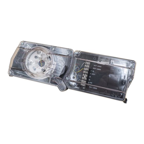
FIGURE 2: The DUCTSD240 detector is designed to operate on 24 VDC/VAC or 120 VAC. REMOVE PIN AND PIVOT REPLACE PIN TO SECURE DETECTOR DETECTOR AS SHOWN BELOW. -
Page 3: Sampling Tube Installation
A plastic exhaust tube is included with the unit to be installed if needed. In- The DUCTSD240 is designed to operate over an extended air speed range of stall into the housing connection that is downstream from the sampling tube 100 to 4000 FPM. -
Page 4: Field Wiring Installation Guidelines
BATTERY 1 WATT RESISTOR 9 VOLT The DUCTSD240 detector is designed for easy wiring. The housing provides a BATTERY terminal strip with clamping plates. See Figure 6 on page 4 for system wiring. *Trouble is indicated when the Supervisory Relay, switches state-Termi-... -
Page 5: Verification Of Operation
• Up to 30 DUCTSD240 units may be interconnected. greater than 500 FPM, use a conventional manometer to measure differential • A combination of DUCTSD240 and D4240 units may be interconnected pressure between the sampling tubes, as described in Section 7.1. -
Page 6: Detector Cleaning Procedures
RTS151/RTS151KEY has cleared the unit will go into STANDBY, otherwise the unit will remain in manual. The DUCTSD240 duct smoke detector can be reset by the RTS151/ ALARM. RTS151KEY. To install the RTS151/RTS151KEY, connect the device as shown in Figure 12;... -
Page 7: Detector Status
Alarm Relay: Terminals 4 and 5 are open Aux Relay does not switch states NOTE: Power Board LED is not visible unless the power board cover is removed. If any other visual indication is noted contact System Sensor technical support at 1-800-SENSOR2. -
Page 8: Warranty
Please refer to insert for the Limitations of Fire Alarm Systems THREE-YEAR LIMITED WARRANTY System Sensor warrants its enclosed product to be free from defects in materials and TX 79936, USA. Please include a note describing the malfunction and suspected cause workmanship under normal use and service for a period of three years from date of of failure.
Need help?
Do you have a question about the DUCTSD240 and is the answer not in the manual?
Questions and answers