Advertisement
Quick Links
INSTALLATION AND MAINTENANCE INSTRUCTIONS
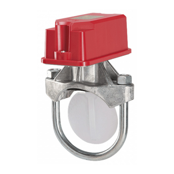
WFDNA Series Vane-type Waterflow
Detectors
SPECIFICATIONS
Contact Ratings:
Triggering Threshold Bandwidth (Flow Rate):
Static Pressure Rating:
Dimensions, Installed:
Operating Temperature Range:
Compatible Pipe:
Shipping Weight:
Enclosure Rating:
U. S. Patent Numbers:
IMPORTANT
Please Read Carefully And Save
This instruction manual contains important information about the installation
and operation of waterflow detectors. Purchasers who install waterflow detec-
tors for use by others must leave this manual or a copy of it with the user.
Read all instructions carefully before beginning. Follow only those instruc-
tions that apply to the model you are installing.
The model WFDNA is a vane-type waterflow detector for use in wet-pipe fire
sprinkler systems only. Vane-type waterflow detectors shall not be used as
the sole initiating device in both deluge and preaction systems; waterflow de-
tectors used in these types of systems may result in an unintended discharge
caused by a surge, trapped air or a short retard time.
Installation must be performed by qualified personnel and in accordance with
all national and local codes and ordinances.
Shock hazard: Disconnect power source before servicing. Serious injury or
death could result.
Risk of explosion: Not for use in hazardous locations. Serious injury or
death could result.
PRINCIPLES OF OPERATION
Vane-type waterflow detectors mount to water-filled pipes in fire sprinkler
systems. Waterflow in the pipe deflects a vane, which produces a switched
output, usually after a specified delay. All WFDNA's have a pneumatically
controlled mechanical delay mechanism. Delays do NOT accumulate; they
reset if the flow of water stops or drops below minimum triggering flow rate
before the entire delay has elapsed.
All switches actuate when the water flow rate is 10 gallons per minute or
greater, but will not actuate if the flow rate is less than 4 gallons per minute.
This System Sensor installation manual covers the following waterflow detec-
tors for fire sprinkler/fire alarm applications.
Pipe Size
Model
(inches)
WFD20NA
2
WFD25NA
2.5
WFD30NA
3
WFD40NA
4
WFD50NA
5
WFD60NA
6
WFD80NA
8
SS-200-035
10 A @ 125/250 VAC
4 to 10 gpm
See models listed below
2.6 in H x 3.5 in W x 6.7 in D
32°F to 150°F (0°C to 66°C)
Steel water pipe, schedule 7 through 40 (See chart below)
3 to 6 lbs (according to size)
NEMA Type 4, as tested by Underwriters Laboratories, Inc.
5,213,205
CAUTION
WARNING
Max. Pressure
Pipe
Schedule
Rating (psig)
7 thru 40
450
7 thru 40
450
7 thru 40
450
7 thru 40
450
10 thru 40
450
10 thru 40
450
10 thru 40
450
6581 Kitimat Road, Unit 6, Mississauga, Ontario L5N-3T5
; 2.5 A @ 24 VDC
Do NOT use any of the WFDNA models on copper pipe. The clamping forces
of the mounting bolts may collapse the pipe sufficiently to prevent the detec-
tor from functioning properly.
Do NOT install steel or iron pipe sections in copper piping for mounting a
waterflow detector. Incompatibility between the dissimilar metals causes bi-
metallic corrosion.
INSTALLATION GUIDELINES
Before installing any waterflow alarm device, be thoroughly familiar with:
NFPA 72: National Fire Alarm Code
NFPA 13: Installation of Sprinkler Systems, Sect. 3.17
NFPA 25: Inspection, Testing and Maintenance of Sprinkler Systems, Sect.
5.3.3.2
CAN/ULC S524: Installation of Fire Alarm Systems
Other applicable Canadian and NFPA standards, local codes, and the re-
quirements of the authority having jurisdiction
NOTE: Installation methods other than those listed in this installation manual
may prevent the device from reporting the flow of water in the event the associ-
ated fire sprinkler system is activated by a fire. System Sensor is not respon-
sible for devices that have been improperly installed, tested, or maintained.
1.
Mount the detector where there is adequate clearance for installation and
removal and a clear view of it for inspections. See Figure 1 for mounting
dimensions.
2.
Locate the detector 6 to 7 feet above the floor to protect from accidental
damage.
3.
On horizontal runs, position the detector on the top or side of the pipe. Do
not mount it upside down because condensation may collect in the hous-
ing and impair the operation of the detector. For vertical flow applications,
mount the detector on pipe through which water flows upward. Otherwise,
the unit may not operate properly.
4.
Mount the detector at least 6 inches from a fitting that changes the direc-
tion of water flow and no less than 24 inches from a valve or drain.
5.
Be sure the direction-of-flow arrows and directional cover match the direc-
tion of flow in the pipe. See Figure 6.
MOUNTING INSTRUCTIONS
1.
Drain the pipe.
2.
Cut a hole in the pipe at the desired location. Center the hole on the pipe,
as shown in Figure 2, and be sure the hole is perpendicular to the center
of the pipe. Before drilling, use a punch or scribe to mark the drill site to
prevent the bit from slipping. If the hole is off center, the vane will bind
against the inside wall of the pipe. Use a drill or hole saw to cut a hole of
the proper diameter. See Table 1 for hole size.
When drilling the hole with a hole saw, make certain that the center of the cut
does not remain in the pipe.
1
1-800-SENSOR2, FAX: 905-812-0771
www.systemsensor.ca
CAUTION
CAUTION
I56-4175-002
Advertisement

Related Manuals for System Sensor WFDNA Series


Summary of Contents for System Sensor WFDNA Series
- Page 1 Risk of explosion: Not for use in hazardous locations. Serious injury or ated fire sprinkler system is activated by a fire. System Sensor is not respon- death could result.
- Page 2 Remove burrs and sharp edges from the hole. Clean and remove all PRE-OPERATION TESTING scale and foreign matter from the inside of the pipe for a distance equal Fill the fire sprinkler system and check for leaks around the waterflow to the pipe diameter on either side of the hole to ensure free movement detector.
- Page 3 System Sensor is not responsible for devices that have been improperly installed, tested, or maintained.
- Page 4 THREE-YEAR LIMITED WARRANTY System Sensor warrants its enclosed waterflow detector to be free from defects in to: System Sensor, Returns Department, RA #__________, 6581 Kitimat Road, Unit 6, Mississauga, Ontario L5N-3T5. Please include a note describing the malfunction and materials and workmanship under normal use and service for a period of three years from date of manufacture.
Need help?
Do you have a question about the WFDNA Series and is the answer not in the manual?
Questions and answers