System Sensor 1424 Installation And Maintenance Instructions
Direct wire ionization smoke detectors
Hide thumbs
Also See for 1424:
Advertisement
Quick Links
INSTALLATION AND MAINTENANCE INSTRUCTIONS
1412 and 1424 Direct Wire
Ionization Smoke Detectors
Specifications
Diameter:
Height:
Weight:
Operating Temperature:
Operating Humidity:
Locking Alarm:
Relay Contact Ratings
Resistive or Inductive (60% power factor) load
Form A:
Form C:*
*For Canadian installations, relay contact rating is 2.0A @ 30VAC/DC
Electrical Ratings:
System Voltage:
Supply Voltages:
Reset Voltages:
Standby Current:
Alarm Currents:
The alarm and auxiliary relay operate within the specified voltage ratings.
Reset Time:
Start-up Time:
Before Installing
Please thoroughly read the System Sensor manual I56-407-
XX, Guide for Proper Use of System Smoke Detectors, which
provides detailed information on detector spacing, place-
ment, zoning, wiring, and special applications. Copies of
this manual are available at no charge from System Sensor.
(For installation in Canada, refer to CAN/ULC-S524, Stan-
dard for the Installation of Fire Alarm Systems and CEC Part
1, Sec. 32.)
General Description
System Sensor 1412 and 1424 dual-chamber ionization
smoke detectors utilize state-of-the-art, unipolar sensing
chambers. These detectors are designed to provide open
area protection, and to be used with UL-listed 4-wire con-
trol panels. The 1412 for 12 volt panels operates at 12VDC,
and the 1424 for 24 volt panels operates at 24VDC. The de-
tectors' operation and sensitivity can be tested in place.
These detectors are listed to UL 268 and are latching type
system detectors. When latched in alarm, the detectors
must be reset by a momentary power interruption.
D400-08-00
Technical Manuals Online! - http://www.tech-man.com
5.5 inches (14 cm)
3.12 inches (8.0 cm)
0.7 lb (310 gm)
0° to +49°C (32° to 120° F)
10% to 93% Relative Humidity Non-condensing
Reset by momentary power interruption.
2.0A @ 30VAC/DC
0.6A @ 110VDC, 2.0A @ 30VDC
1.0A @ 125VAC, 2.0A @ 30VAC
1412
12
11.3
17.3
.73
100
35.2
77.0
0.3
30
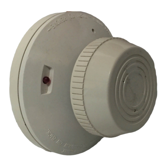
An LED on the detector provides a local indication of the
detector's status. If power is applied to the detector, and the
detector is functioning properly in standby, the status LED
will blink every 10 seconds. In alarm, the LED will be
latched on continuously until the detector is reset.
Each detector contains one Form A (SPST-NO) contact for
connection to the alarm-initiating circuit, and one Form C
(SPDT-NO/NC) set of auxiliary contacts. Supervision of de-
tector power is accomplished by installing a Power Supervi-
sory End-of-Line Relay Module (A77-716) at the end of the
detector power loop. When power is applied to and
through the detectors, the EOL Power Supervisory Module
is energized. Its relay contacts close and provide a closed
series circuit in the control panel's alarm-initiating loop. A
power failure or a break in the detector power loop de-ener-
gizes the EOL Module. The relay contacts open and trigger
a trouble signal at the control panel.
1
3825 Ohio Avenue, St. Charles, Illinois 60174
1-800-SENSOR2, FAX: 630-377-6495
1424
24
DC (4V Maximum Ripple)
20
VDC Minimum
29
VDC Maximum
.8
VDC Minimum
µ A Maximum
100
21.3
mA Minimum
40.6
mA Maximum
0.3
Seconds
30
Seconds
A Division of Pittway
I56-280-03
Advertisement

Related Manuals for System Sensor 1424


Summary of Contents for System Sensor 1424
- Page 1 The 1412 for 12 volt panels operates at 12VDC, series circuit in the control panel’s alarm-initiating loop. A and the 1424 for 24 volt panels operates at 24VDC. The de- power failure or a break in the detector power loop de-ener- tectors’...
- Page 2 Figure 3. Wiring diagram for models 1412 and 1424 detectors used with Class A or Class B four-wire control panels. POWER...
- Page 3 (see Figure 2), then install the Detectors must be tested after installation and following detector. To remove the detector from the bracket once the periodic maintenance. The 1412 and 1424 may be tested as tamper-proof feature has been activated, depress the follows: tamper-proof tab located in the slot on the mounting A.
- Page 4 NFPA 72 or at least once a year. Three-Year Limited Warranty System Sensor warrants its enclosed smoke detector to be free from de- ment, RA #__________, 3825 Ohio Avenue, St. Charles, IL 60174. Please include a note describing the malfunction and suspected cause of failure.
Need help?
Do you have a question about the 1424 and is the answer not in the manual?
Questions and answers