Table of Contents
Advertisement
Quick Links
Advertisement
Table of Contents

Related Manuals for AXIOMTEK FDK series


Summary of Contents for AXIOMTEK FDK series
- Page 1 FDK Series 15” 17” 19” Flexible Display Panel PC User’s Manual...
- Page 2 AXIOMTEK does not warrant or assume any legal liability or responsibility for the accuracy, completeness or usefulness of any information in this document. AXIOMTEK does not make any commitment to update the information in this manual.
-
Page 3: Safety Approvals
Safety Approvals CE Marking FCC Class A FCC Compliance This equipment has been tested in compliance with the limits for a Class A digital device, pursuant to Part 15 of the FCC Rules. These limits are meant to provide reasonable protection against harmful interference in a residential installation. -
Page 4: Safety Precautions
Safety Precautions Before getting started, please read the following important safety precautions. The FDK does not come equipped with an operating system. An operating system must be loaded first before installing any software into the computer. Be sure to ground yourself to prevent static charge when installing the internal components. - Page 5 When handling boards and components, wear a wrist- grounding strap, available from most electronic component stores. Trademarks Acknowledgments AXIOMTEK is a trademark of AXIOMTEK Co., Ltd. IBM, PC/AT, PS/2, VGA are trademarks of International Business Machines Corporation. ® ™...
-
Page 6: Table Of Contents
Table of Contents Disclaimers ................ii Safety Approvals ..............iii Safety Precautions.............. iv CHAPTER 1 INTRODUCTION ......... 1 General Description ..........1 Specifications ............2 1.2.1 Main CPU Board ............2 ... - Page 7 Chipset Menu ............ 57 Exit Menu ............62 CHAPTER 4 DRIVERS INSTALLATION ..... 64 System .............. 64 Touch Screen ........... 65 4.2.1 Specification .............. 65 4.2.2 Driver Installation- Windows XP ....... 65 ...
- Page 8 MEMO viii...
-
Page 9: Chapter 1 Introduction
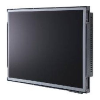
Dimensions I/O Outlets Package List General Description The FDK series is an open frame touch panel computer, equipped ○ with a TFT LCD display and low power consumption Intel Atom N270 1.6GHz processor with FSB 533MHz. The FDK series supports ®... -
Page 10: Specifications
FDK series User’s Manual unit incorporates a Mini Card slot for expansion capability. Specifications 1.2.1 Main CPU Board ○ Intel Atom N270 1.6GHz processor with FSB 533MHz onboard System Chipset 945GSE + ICH7M BIOS America Megatrends BIOS System Memory One 200-pin DDR2 SO-DIMM socket Maximum memory up to 2GB 1.2.2 I/O System... -
Page 11: System Specification
FDK User’s Manual 1.2.3 System Specification 15”(1024x768), 17”(1280x1024), or 19”(1280x1024) TFT One VR for brightness control Touch (equip on FDK1x0-830-R models) 5-wired resistive touch Heat Dispensing Design Disk drive housing: One 2.5” SATA drive Net Weight 3.84 Kgs (8.46 lb) (FDK150-830-R) 5.52 Kgs (12.16 lb) (FDK170-830-R) 5.82 Kgs (12.83 lb) (FDK190-830-R) Dimension (Main Body Size) -
Page 12: Product List
FDK series User’s Manual Product List FDK series provides three sizes of LCD, 15”, 17”, and 19”. The touch screen is optional. Please refer to the following table. Product Name LCD Size Resolution Touch FDK150-830-N 15” 1024 x 768 FDK150-830-R 15”... -
Page 13: Dimensions
FDK User’s Manual Dimensions FDK150-830-N without touch dimensions Introduction... - Page 14 FDK series User’s Manual FDK150-830-R with touch dimensions Introduction...
- Page 15 FDK User’s Manual FDK170-830-N without touch dimensions Introduction...
- Page 16 FDK series User’s Manual FDK170-830-R with touch dimensions Introduction...
- Page 17 FDK User’s Manual FDK190-830-N without touch dimensions Introduction...
- Page 18 FDK series User’s Manual FDK190-830-R with touch dimensions Introduction...
-
Page 19: I/O Outlets
FDK User’s Manual I/O Outlets Please refer to the following illustration for I/O locations of the FDK. Function Function POWER SWITCH (ATX) COM 2 (RS-232) Power Input connector (phoenix type) 2 X USB 2.0 1X ETHERNET (RJ-45) COM 3 (RS-232) 2 X USB 2.0 COM 4 (RS-232) AUDIO (LINE-OUT) -
Page 20: Packing List
FDK series User’s Manual Packing List When you receive the FDK, the bundled package should contain the following items: FDK unit x 1 Driver CD x1 SATA cable x 1 SATA power cable x 1 Phoenix connector x 1 If you can not find the package or any items are missing, please contact AXIOMTEK distributors immediately. -
Page 21: Chapter 2 Hardware Installation
FDK series User’s Manual CHAPTER 2 HARDWARE INSTALLATION The FDK series provides rich I/O ports and flexible expansions for you to meet different demand, for example, CF card. The chapter will show you how to install the hardware. It includes: ™... - Page 22 FDK series User’s Manual Step 2 When users open the back cover, there is a cable connecting between a fan and the motherboard. Hardware Installation...
- Page 23 FDK series User’s Manual Step 3 Remove the connector first before remove the back cover totally. Step 4 After removing the back cover, users can see the inside of the unit. Hardware Installation...
- Page 24 FDK series User’s Manual Step 5 Before closing the back cover, users must connect the fan cable to the motherboard first. Step 6 Then close back cover and fix back the eleven screws. Hardware Installation...
-
Page 25: Cf Card Installation
FDK series User’s Manual CF card Installation The FDK series provides one CF slot for users to install ™ CompactFlash card. Please refer to the following instructions for installation: Step 1 Turn off the system, and unplug the power cord. - Page 26 FDK series User’s Manual Hardware Installation...
-
Page 27: Serial Ports Interface
FDK series User’s Manual Serial Ports Interface The FDK has four serial ports. COM1 is RS-232/422/485, while COM2, COM3, and COM4 are RS-232. The following table shows you the pin assignments of this connector: Signal Signal Data Carrier Detect (DCD) - Page 28 FDK series User’s Manual When COM1 is set to RS-422 or RS-485, the pin assignments are listed below: Signal Name Pin # RS-422 RS-485 DATA- DATA+ No connector No connector No connector No connector No connector No connector No connector...
-
Page 29: Ethernet
FDK series User’s Manual Ethernet The FDK is equipped with a high performance Plug and Play Ethernet interface, full compliant with IEEE 802.3 standard, and can be connected with a RJ-45 LAN connector. Please refer to detailed pin assignment list below:... -
Page 30: Openframe And Vesa Mountings
There are two mounting ways for the FDK series, openframe and VESA mountings. 2.4.1 Openframe Mounting The FDK series can be mounted into the wall or put on customized front bezel. Please follow the steps below to for the open frame mounting installation. -
Page 31: Vesa Mounting
FDK series User’s Manual 2.4.2 VESA Mounting FDK series provides two types of VESA holes, 75mm x 75mm and 100mm x 100mm. These VESA holes can easy for users to install FDK seris via many different types of VESA mounting holders, such as VESA arm, VESA wall holders…etc. -
Page 32: Hdd Installation
FDK series User’s Manual HDD Installation The FDK provides a convenient Hard Disk Drive (HDD) bracket for users to install 2.5” SATA HDD. Please follow the steps: Step 1 Refer section 2.1 to open the back cover. Step 2 Unscrew 4 screws to take off the HDD bracket. - Page 33 FDK series User’s Manual Step 4 Fix the HDD bracket into the system, and plug the data and power cable to HDD. Installation completes. Data Powe Hardware Installation...
-
Page 34: Dram Installation
FDK series User’s Manual DRAM Installation The FDK provides one 200-pin DDR2 SODIMM socket that support system memory up to 2GB. Please follow steps below to install the memory modules: Step 1 Refer to section 2.1 to open the back cover and find out DIMM socket on mainboard (SBC87830). - Page 35 FDK series User’s Manual Step 3 Installation completes. Hardware Installation...
-
Page 36: Wireless Lan Card Installation
FDK series User’s Manual Wireless LAN Card Installation The FDK provides one Mini card slot for user to install one wireless LAN card. When installing the wireless LAN card, refer to the following instructions and illustration: Step 1 Refer to section 2.1 to open the back cover and find out mini-card slot on mainboard. - Page 37 FDK series User’s Manual Step 3 Remove the antenna plug from the top of back cover. Step 4 Install the antenna cable on the back cover. Hardware Installation...
- Page 38 FDK series User’s Manual Step 5 Install the antenna on the antenna connector. Step 6 Connect the antenna cable to wireless LAN card. Hardware Installation...
- Page 39 FDK series User’s Manual MEMO Hardware Installation...
-
Page 40: Chapter 3 Ami Bios Setup Utility
FDK series User’s Manual CHAPTER 3 AMI BIOS SETUP UTILITY This chapter provides users with detailed description how to set up basic system configuration through the AMI BIOS setup utility. Starting To enter the setup screens, follow the steps below: Turn on the computer and press the <Del>... -
Page 41: Main Menu
FDK series User’s Manual The <F10> key allows you to save any changes you have made and exit Setup. Press the <F10> key to save your changes. The <Esc> key allows you to discard any changes you have made and exit the Setup. Press the <Esc>... -
Page 42: Advanced Menu
FDK series User’s Manual System Time or System Date using the <Arrow> keys. Enter new values through the keyboard. Press the <Tab> key or the <Arrow> keys to move between fields. The date must be entered in MM/DD/YY format. The time is entered in HH:MM:SS format. - Page 43 FDK series User’s Manual Configure advanced CPU settings This screen shows the CPU Configuration, and you can change the value of the selected option. Max CPUID Value Limit You can enable this item to let legacy operating systems boot even without support for CPUs with extended CPU ID functions.
- Page 44 FDK series User’s Manual Use this item to enable or disable the C-State technology. Enhanced C-States This item allows you to enable or disable any available enhanced C-states ( C1E, C2E, C3E, C4E and Hard C4E). IDE Configuration You can use this screen to select options for the IDE Configuration, and change the value of the selected option.
- Page 45 FDK series User’s Manual installed in the system by pressing <Enter> for more options. SuperIO Configuration You can use this screen to select options for the SuperIO Configuration, and change the value of the selected option. A description of the selected item appears on the right side of the screen.
- Page 46 FDK series User’s Manual Serial Port2 IRQ This item specifies the IRQ used by the serial port 2. Serial Port3 Address This item specifies the base I/O port address and Interrupt Request address of serial port 3. Serial Port3 IRQ This item specifies the IRQ used by the serial port 3.
- Page 47 FDK series User’s Manual Hardware Health Configuration This screen shows the Hardware Health Configuration, and a description of the selected item appears on the right side of the screen. System Temperature/CPU Temperature These items display the temperature of CPU and System, Vcore, etc.
- Page 48 FDK series User’s Manual ACPI Settings You can use this screen to select options for the ACPI Settings, and change the value of the selected option. A description of the selected item appears on the right side of the screen.
- Page 49 FDK series User’s Manual APM Configuration You can use this screen to select options for the APM Configuration, and change the value of the selected option. A description of the selected item appears on the right side of the screen.
- Page 50 FDK series User’s Manual expired. The default setting is Suspend. This setting prevents the BIOS from initiating Disabled any power saving modes concerned with the video display or monitor. This option places the monitor into suspend mode after the specified period of display inactivity has expired.
- Page 51 FDK series User’s Manual default setting is On/Off. Pushing the power button turns the computer On/Off on or off. This is the default setting. This is the default setting. Pushing the power button places the computer Suspend in Suspend mode or Full On power mode.
- Page 52 FDK series User’s Manual MPS Configuration This screen shows the MPS (Multi Processor Specification) Configuration, and you can change its value. A description of the selected item appears on the right side of the screen. MPS Revision Use this item to select MPS (Multi Processor Specification) Revision 1.1 or 1.4.
- Page 53 FDK series User’s Manual PCI Express Configuration This screen shows the PCI Express Configuration, and you can change its value. A description of the selected item appears on the right side of the screen. Active State Power-Management Use this item to enable or disable the function of Active State Power-Management to provide you with lower power consumption.
- Page 54 FDK series User’s Manual USB Configuration You can use this screen to select options for the USB Configuration, and change the value of the selected option. A description of the selected item appears on the right side of the screen.
-
Page 55: Pci Pnp Menu
FDK series User’s Manual PCI PnP Menu The PCI PnP menu allows users to change the advanced settings for PCI/PnP devices. AMI BIOS Setup Utility... - Page 56 FDK series User’s Manual Clear NVRAM Use this item to clear the data in the NVRAM (CMOS). Here are the options for your selection, No and Yes. Plug & Play O/S When the setting is No, Use this item to configure all the devices in the system.
- Page 57 FDK series User’s Manual and Yes. Palette Snooping Some old graphic controllers need to “snoop” on the VGA palette, and then map it to their display as a way to provide boot information and VGA compatibility. This item allows such snooping to take place. Here are the options for your selection, Disabled and Enabled.
-
Page 58: Boot Menu
FDK series User’s Manual Boot Menu The Boot menu allows users to change boot options of the system. You can select any of the items in the left frame of the screen to go to the sub menus: Boot Settings Configuration... - Page 59 FDK series User’s Manual Boot Settings Configuration Quick Boot Enabling this item lets the BIOS skip some power on self tests (POST). The default setting is Enabled. Quiet Boot Set this item to allow the computer system Disabled to display the POST messages.
- Page 60 FDK series User’s Manual IRQ. Here are the options for your selection, Auto, Enabled and Disabled. Wait For ‘F1’ If Error If this item is enabled, the system waits for the F1 key to be pressed when error occurs. The default setting is Enabled.
- Page 61 FDK series User’s Manual Removable Drives Use this screen to view the removable drives in the system. The BIOS will attempt to arrange the removable drive boot sequence automatically. You can also change the booting sequence. AMI BIOS Setup Utility...
- Page 62 FDK series User’s Manual Lan Boot Settings Configuration The Lan Boot Settings Configuration can enable or disable Lan Boot ROM to allow the system boot on LAN. AMI BIOS Setup Utility...
-
Page 63: Security Menu
FDK series User’s Manual Security Menu The Security menu allows users to change the security settings for the system. Supervisor Password This item indicates whether a supervisor password has been set. If the password has been installed, Installed displays. If not, Not Installed displays. - Page 64 FDK series User’s Manual menu. You can use the sub menu to change the user password. Boot Sector Virus Protection This option is near the bottom of the Security Setup screen. The default setting is Disabled. Set this item to prevent the Boot Sector Virus Disabled Protection.
-
Page 65: Chipset Menu
FDK series User’s Manual Chipset Menu The Chipset menu allows users to change the advanced chipset settings. You can select any of the items in the left frame of the screen to go to the sub menus: North Bridge Configuration South Bridge Configuration For items marked with “... - Page 66 FDK series User’s Manual North Bridge Configuration DRAM Frequency This item allows you to control the Memory Clock. Configure DRAM Timing by SPD This item can enable or disable DRAM timing by SPD (Serial Presence Detect) device, which is a small EEPROM chip on...
- Page 67 FDK series User’s Manual AMI BIOS Setup Utility...
- Page 68 FDK series User’s Manual South Bridge Configuration AMI BIOS Setup Utility...
- Page 69 FDK series User’s Manual USB Function This item allows you to enable or disable USB function. USB 2.0 Controller This item allows you to enable or disable the USB 2.0 controller. Audio Controller This item allows you to enable or disable the audio support.
-
Page 70: Exit Menu
FDK series User’s Manual This item allows you to set or disable the PCI Express Ports. Exit Menu The Exit menu allows users to load your system configuration with optimal or failsafe default values 0 Save Changes and Exit When you have completed the system configuration... - Page 71 FDK series User’s Manual Use this item to abandon all changes. Load Optimal Defaults It automatically sets all Setup options to a complete set of default settings when you select this option. The Optimal settings are designed for maximum system performance, but may not work best for all computer applications.
-
Page 72: Chapter 4 Drivers Installation
FDK series User’s Manual CHAPTER 4 DRIVERS INSTALLATION System FDK supports Windows 2000/XP. To facilitate the installation of system driver, please carefully read the instructions in this chapter before start installing. Insert Driver CD and select the “\Drivers”. Select all files and follow the installing procedure. -
Page 73: Touch Screen
FDK series User’s Manual Touch Screen The FDK uses the 5-wire analog resistve. There are the specification and driver installation which are listed below. 4.2.1 Specification Touch Screen 5-wire Analog Resistive type Touch Screen Controller PenMount 6000 USB Touch Screen Controller IC... - Page 74 FDK series User’s Manual Click Start menu and select “PenMount Utilities”; and then, a “PenMount Control Panel” pops out. Installation of Drivers...
- Page 75 FDK series User’s Manual Select the “Standard Calibrate” tab. Calibration: To adjust the display with touch panel, click “Calibration” and follow the calibrate point to do calibration; there are five points on screen for calibration. Press OK. Installation of Drivers...
-
Page 76: Embedded O.s
FDK series User’s Manual Embedded O.S. The FDK provides the Windows XP Embedded and Windows CE.Net 6.0. The O.S. is supported devices which are listed below. 4.3.1 Windows XP Embedded Here are supported onboard devices: Onboard Multi I/O SATA HDD...
Need help?
Do you have a question about the FDK series and is the answer not in the manual?
Questions and answers