Table of Contents
Advertisement
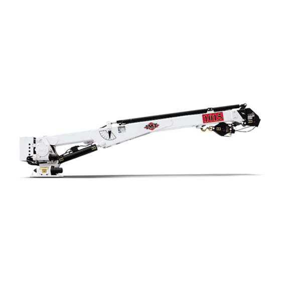
99903514:TELESCOPIC CRANE:
20140915
i
SECTION 0: INTRODUCTION
VOLUME 1
TELESCOPIC CRANE
OPERATION AND SAFETY
IOWA MOLD TOOLING CO., INC.
BOX 189, GARNER, IA 50438-0189
TEL: 641-923-3711
TECHNICAL SUPPORT FAX: 641-923-2424
MANUAL PART NUMBER 99903514
Iowa Mold Tooling Co., Inc. is an Oshkosh Corporation Company.
Advertisement
Chapters
Table of Contents
Troubleshooting


Need help?
Do you have a question about the 1015 and is the answer not in the manual?
Questions and answers