Table of Contents
Advertisement
Quick Links
Advertisement
Table of Contents

Related Manuals for IMT 28562


Summary of Contents for IMT 28562
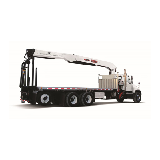
- Page 1 99903701:24562/28562INSTALLATION:20131211 PARTS-1 Model 24562/28562 Crane INSTALLATION MANUAL IOWA MOLD TOOLING CO., INC. BOX 189, GARNER, IA 50438-0189 641-923-3711 MANUAL PART NUMBER: 99903701 Iowa Mold Tooling Co., Inc. is an Oshkosh Truck Corporation company.
- Page 2 99903701:24562/28562INSTALLATION:20131211 PARTS-2 In addition to the information presented in this manual, read and understand the IMT Crane Operator's Safety Manual before operating or performing any maintenance on your crane. REVISIONS LIST DATE LOCATION DESCRIPTION OF CHANGE 20050421 NEW MANUAL RELEASE...
- Page 3 Sterling chassis and assumes no interferences with Unique Crane Applications: Units mounted on non- the crane. Sterling chassis may require unique handling. Consult IMT if the unit is not compatible with these NOTE instructions. ALL APPLICABLE LEGAL HEIGHT, LENGTH, WIDTH AND WEIGHT LIMITS ARE THE RESPONSIBILITY OF THE INSTALLER.
- Page 4 Steel stock of 1/8, 3/16 and 1/4” in thickness is the most commonly used. The IMT kit does not include the shim stock since only a small percentage of the Figure 2: Areas which may require shims trucks need to have the shims installed.
- Page 5 99903701:24562/28562INSTALLATION:20131211 PARTS-5 STEP III. CRANE PREPARATION Measure the tie rod pockets on the stabilizer side of the crane, as shown in figure 4. Use a square and a level to make sure the pockets are level and true to 1/ 16".
- Page 6 (use hammer if necessary). Custom fit each corner of the mount. If the crush tube causes installation interference, consult IMT. Weld retaining “L” (angle) bracket (P/N 60128035) onto the tube. After the crane is tightened down, drill a hole for 1/2”...
- Page 7 99903701:24562/28562INSTALLATION:20131211 PARTS-7 STEP VI. GUSSET STOP BLOCK INSTALLATION The gusset stop blocks (P/N 60128954) are welded to the crane only. The gusset stop blocks prevent the crane from twisting on the truck frame. On the rear side of the crane, the gusset stop block must be welded to the reinforced area, not the area where the surface steps down.
- Page 8 While conducting the crane inspection, monitor the clamp plates for movement. If the clamp plates have moved, the entire mount should be inspected. Possible corrective action may be necessary- consult IMT for assistance. Figure 10: Mark painted across the frame and clamp...
Need help?
Do you have a question about the 28562 and is the answer not in the manual?
Questions and answers