Table of Contents
Advertisement
Quick Links
Instruction Manual
C
T
ROSS
ECHNOLOGIES, INC.
C KU
DC ALARM
LO
Data, drawings, and other material contained herein are proprietary to Cross Technologies, Inc.,
but may be reproduced or duplicated without the prior permission of Cross Technologies, Inc.
for purposes of operating the equipment. Printed in USA.
When ordering parts from Cross Technologies, Inc., be sure to include the equipment
model number, equipment serial number, and a description of the part.
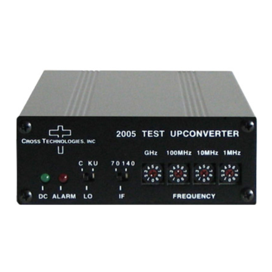
2005 TEST CONVERTER
GHz
100MHz
10MHz
1MHz
70 140
FREQUENCY
IF
C
T
ROSS
ECHNOLOGIES, INC.
6170 Shiloh Road
Alpharetta, Georgia 30005
(770) 886-8005
FAX (770) 886-7964
Toll Free 888-900-5588
WEB: www.crosstechnologies.com
E-MAIL: info@crosstechnologies.com
Model 2005-10-01
C
T
ROSS
ECHNOLOGIES, INC.
IF
DC POWER
J1
J3
Upconverter
October 2013, Rev. A
RF
J2
Advertisement
Table of Contents

Related Manuals for Cross Technologies 2005


Summary of Contents for Cross Technologies 2005
- Page 1 DC ALARM Data, drawings, and other material contained herein are proprietary to Cross Technologies, Inc., but may be reproduced or duplicated without the prior permission of Cross Technologies, Inc. for purposes of operating the equipment. Printed in USA. When ordering parts from Cross Technologies, Inc., be sure to include the equipment model number, equipment serial number, and a description of the part.
-
Page 2: Table Of Contents
WARRANTY - The following warranty applies to all Cross Technologies, Inc. products. All Cross Technologies, Inc. products are warranted against defective materials and workmanship for a period of one year after shipment to customer. Cross Technologies, Inc.’s obligation under this warranty is limited to repairing or, at Cross Technologies, Inc.’s option, replacing parts, subassemblies, or entire assemblies. -
Page 3: General
2000 to 2500 MHz in 1 MHz steps with selection of high side LO (C = inverted) or low side LO (Ku = non-inverted) and 70 or 140 MHz input over the 2.0 - 2.5 GHz range. The 2005-10-01 allows for an input level range of +10 to -15 dBm. -
Page 4: Technical Characteristics
1.2 Technical Characteristics TABLE 1.0 2005-10-01 Upconverter Specifications* Input Characteristics Impedance 50Ω Return Loss 15 dB Frequency 70 or 140 MHz center, ±20 MHz Level +10 to -15 dBm 1dB compression +15 dBm Output Characteristics Impedance 50Ω Return Loss 12 dB Frequency Range 2.0 to 2.5 GHz... -
Page 5: Installation
2.1 Mechanical The 2005-10-01 is packaged in an aluminum extrusion. The -R option is mounted on a 1 3/4” X 19” panel that can be mounted to a rack using the 4 holes at the ends. The unit derives +DC from the wall power supply (+15V unregulated, or regulated universal -P4). -
Page 6: Accessing The Pc Card
2.5.1 Installing and Operating the 2005-10-01 1. If using the receiver LNB voltage to power the 2005-10-01, be sure +14 to +24 VDC is on the RF center conductor. If using the wall power supply (options -P or -P4), connect the power supply to the DC POWER connector and either 120 ±10% (-P) or 100-240 ±10% VAC (-P4) (Figure 2.2) -
Page 7: Environmental Use Information
G. Top Cover - There are no serviceable parts inside the product so, the Top Cover should not be removed. If the Top Cover is removed the ground strap and associated screw MUST BE REINSTALLED prior to Top Cover screw replacement. FAILURE TO DO this may cause INGRESS and/or EGRESS emission problems. 2005-10-01 Manual, Rev. A Page 7 10/30/2013... -
Page 8: Shiloh Road Alpharetta, Georgia
ROSS ECHNOLOGIES, INC. 6170 Shiloh Road Alpharetta, Georgia 30005 (770) 886-8005 FAX (770) 886-7964 Toll Free 888-900-5588 WEB: www.crosstechnologies.com E-MAIL: info@crosstechnologies.com Printed in USA 2005-10-01 Manual, Rev. A Page 8 10/30/2013...
Need help?
Do you have a question about the 2005 and is the answer not in the manual?
Questions and answers