Table of Contents
Advertisement
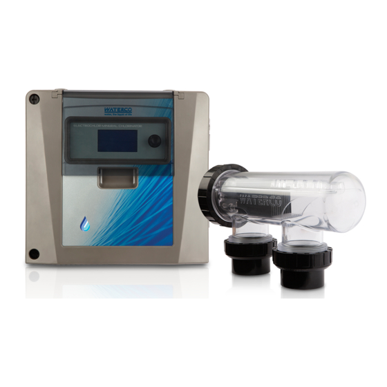
ELECTROCHLOR
Mineral Chlorinator
Owner's Manual
This equipment must be installed and serviced by a qualified technician.
WARNING
!
Improper installation can create electrical hazards which could result in
property damage, serious injury or death. Improper installation will void the
Notice to Installer
This manual contains important information about the installation, operation
and safe use of this product. Once the product has been installed this manual
must be given to the owner/operator of this equipment.
®
www.waterco.com.au
Advertisement
Table of Contents

Related Manuals for Waterco ELECTROCHLOR


Summary of Contents for Waterco ELECTROCHLOR
- Page 1 ELECTROCHLOR ® Mineral Chlorinator Owner's Manual This equipment must be installed and serviced by a qualified technician. WARNING Improper installation can create electrical hazards which could result in property damage, serious injury or death. Improper installation will void the warranty.
-
Page 2: Table Of Contents
Table of geNerAl SAFeTy ruleS WHAT’S IN THe bOX? 2. INTrOduCTION 3. INSTAllATION 4. PrOgrAMINg THe eleCTrOCHlOr 5. MAINTeNANCe 6. AlArMS reCOMMeNded WATer CHeMISTry 8. TrOubleSHOOTINg guIde 9. TeCHNICAl SPeCIFICATIONS 10. WArrANTy 11. ICONS lIST 12. MeNu Tree... - Page 3 Warning electrochlor should be deactivated if the pool or spa has been drained. Parts incorporating electrical components, except remote control devices, Warning must be located or fixed so that they cannot fall into the spa – pool.
-
Page 4: General Safety Rules
Mineral Chlorinator 04 I GENERAL SAFETY RULES The equipment mentioned in this manual is specially designed for the sanitizing of water in swimming pools. 2. It is designed to work with clean water at a temperature not exceeding 35°C (95°F). -
Page 5: What's In The Box
Mineral Chlorinator I 05 1. WHAT’S IN THE BOX? • electrochlor Power Pack • Owner’s Manual • Warranty booklet If bought as Salt Water Chlorinator unit, the electrolytic cell is provided in NOTE: a separate carton. -
Page 6: Introduction
Self-Cleaning Cell - How it works The electrochlor Power Pack powers up the salt cell (anode and cathode) and holds an electrical potential difference between them for a designated period of time. This difference is reversed after that period of time has expired and then the anode becomes the cathode and the cathode becomes the anode. - Page 7 The Power Pack comes with a battery incorporated to save your settings in the event of a power failure. Pump Protection In case flow is not detected, electrochlor will shut down the pump to protect it. It also displays an alarm indicating the condition. Salt Alarms If the salt level is too low or too high, electrochlor will reduce the output and display the corresponding alarm.
- Page 8 Low Flow Condition In the event of a “no-flow” condition electrochlor will increase the pump speed to try overcome it. If the “no-flow” condition is resolved, the electrochlor will keep the new speed to maintain water flow. This feature is only enable when a Waterco variable speed...
-
Page 9: Installation
Mineral Chlorinator I 09 3. INSTALLATION Ensure that the electrolytic cell is the last piece of equipment installed Warning on the filtration system – this is so the chlorine produced will not damage other equipment such as heaters. The electrolytic cell may be installed above or below water level. If it is... - Page 10 Mineral Chlorinator 10 I 2. To access the electrochlor for connection of cabling and sensors, there are screw wells in each corner of the front panel. To open the panel, insert a flat blade screw driver and half turn anti-clock wise to release the spring loaded locking pin. ensure the pins are fully released prior to opening the hinged front panel.
- Page 11 Mineral Chlorinator I 11 The PUMP socket outlet in the base of the Power Pack is dedicated Warning to the filtration pump only. Do not use a double adaptor to connect another pump as this will overload the system and void warranty.
- Page 12 Mineral Chlorinator 12 I GAS TRAP 40/50mm glued connections Sell Clean Requires Minimum Maintenance The cell must be positioned in such a way as to provide a gas trap. The GAS TRAP: bottom of the cell must be above the top surface of the pipe from the previous piece of equipment, as per the diagram above.
- Page 13 NOTE: glued or tightened securely to prevent leaking. NOTE: Allow 24 hours for glue (solvent) to set before starting the Electrochlor. Installing Temperature Sensor The pool water temperature sensor should be installed prior to any heater or solar. 2. Immediately after the filter drill a 9.5mm hole in the side of the line as shown in the image below.
- Page 14 Mineral Chlorinator 14 I Incorrect Position Correct Position Pool Sensor Installation 4. Insert the sensor holder by pushing into the plug fully up to the head. This is a tight fit to ensure sealing. lubricate with soap if necessary but do not use mineral oil or grease.
- Page 15 I 15 Connection of Communication Cable to Waterco ECO Pumps Waterco eCO pumps may be purchased with the communication cable fitted. Consult your local Waterco sales office for order details. Step 1 – unscrew the 3 x Philips head screws holding the control housing to the motor.
- Page 16 Mineral Chlorinator 16 I Step 6 – Connect the communication cable the main board of the electrochlor into the Waterco eCO pumps socket. Variable Speed Pumps Socket Valve Actuator Socket low Chlorine/ Pool Cover Socket Main board showing eCO Pumps Socket, Valve Actuator and low Chlorine/Pool cover connections.
- Page 17 This function can also be triggered by Waterco’s Aquamaster, whenever the Spa mode in activated. This mode can be activated automatically by connecting a Normally Open (N.O),/...
-
Page 18: Programing The Electrochlor
4. PROGRAMING THE ELECTROCHLOR a. The Wheel (rotary Index Switch (rIS)) located in the upper right side of the electrochlor Power Pack there is a wheel that is used to control the instrument. The wheel can be rotated in both directions to scroll over the menus and/or pressed to confirm a highlighted selection/value. - Page 19 Mineral Chlorinator I 19 b. The Screen electrochlor lCd screen was designed to present to the user the most critical information of the operation of the equipment continuously. The main screen displays the current time, pool temperature, pool pump status, and chlorine production level (when pump is on) among others.
- Page 20 The electrochlor will resume normal programming functions with the next timer cycle if AuTO or WINTer modes are active. d. Operating Modes: Accessing electrochlor Modes: rotate or push the wheel to access menu. locate the MOde menu. Press the wheel to enter menu.
- Page 21 Mineral Chlorinator I 21 electrochlor has the following operating modes: Auto Mode (AUTO): This is the default operation mode. Timers are operational according to programmed settings. Manual Mode (MANUAL): This mode overrides the Timer settings. The electrochlor can only operates in STANdby or ON mode.
- Page 22 Accessing electrochlor Timer menu: rotate or push the wheel to access menu. locate the TIMe menu, then press the wheel to access it. electrochlor has a digital clock and 4 independent timers. each of the timers can be programmed independently to have different behaviour and control...
- Page 23 Mineral Chlorinator I 23 Programming the digital clock. In the TIMe menu rotate the wheel until the ClOCK menu is located, then press the wheel to access it. Setting the time: • Select hours or minutes, rotate the wheel to the desire value. Then press to confirm.
- Page 24 Mineral Chlorinator 24 I • To exit without saving select X and press the wheel. Setting the Chlorine Output The output of the chlorinator can be adjusted to reflect the different seasonal requirements in order to maintain satisfactory chlorine sanitiser levels.
- Page 25 Mineral Chlorinator I 25 g. Controlling the lights: To Switch the light ON/OFF rotate or press the wheel to access menu. locate the lIgHT icon on the menu, then press the wheel to confirm. lIgHT ON indicates the pool light(s) is (are) “ON”. lIgHT OFF indicates the pool light(s) is (are) “off”.
- Page 26 In order to navigate through the setting options, use the wheel to select the arrows (either -> or <-), to cycle through the menu. defining Pump Type electrochlor is designed to work with single speed pumps and variable speed pumps.
- Page 27 This also can be used to interlock functions. Please refer to the Interlock section below for more information. Only one pump can be plug to the Electrochlor GPO or else the combined amperage will exceed the chlorinator's maximum. The only...
- Page 28 Mineral Chlorinator 28 I ii. defining Output 1 (AuX2) electrochlor AuX2 output can be set to behave differently and adapt to the users requirement. It can be set to control: • basic light, in this case it switches on/off the light •...
- Page 29 “no show” to allow only control via timers. vi. Calibrating/defining Temperature units electrochlor has an option to define the temperature units and calibrate the reading. To select the temperature units, enter to settings and navigate to Pool Temperature, select Pool Temperature and select the desired units (Celsius/Fahrenheit degrees).
- Page 30 Menu: The diagnostic menu allows the user to quickly evaluate the current state of the electrochlor. It provides a picture of all the functions that are active at any given the moment. To access to the diagnostic menu, rotate the wheel until you find the dIAgNOSTIC menu and press the wheel to select.
- Page 31 Mineral Chlorinator I 31 Page 1 of diagnostic Screen Page 2 of diagnostic Screen Page 3 of diagnostic Screen...
- Page 32 The Pump Output (Auxiliary 2) can be made available for a secondary pump. This will only be possible, when a variable speed pump is connected to an external and suitable gPO/output. This feature is only available when a VSd pump is in use and connected to electrochlor via a communication cable. Functionality: •...
- Page 33 Any combination can be set to turn on via timer programming lock: Output interlocked On: output make available via timer. Requirements: The electrochlor Interlock Kit is required in order to access full interlock functionality. electrochlor Interlock Kit Content: • Waterco FPI Valve Actuator •...
- Page 34 This also puts a restriction defining the pump speed in the timer. If the minimum speed does not fulfill the pre-set requirements, electrochlor won’t allow the interlocking function. This is to ensure that the minimum water flow is provided for the ancillary function to operate.
- Page 35 This function is only available for variable speed pumps connected to chlorinator through a communication cable. 1) If after priming a “no-flow “condition is detected electrochlor activates “low Flow” condition detection mode automatically. 2) electrochlor activates the pool pump again, this time increasing the programmed speed to the next higher level.
-
Page 36: Maintenance
VIII. Set the time back to original “ON” or “AuTO” position on the power pack to reactivate the electrochlor. Never use products that are not specifically manufactured to clean the Electrochlor’s salt cell. Do not use raw acids such as Hydrochloric acid. Warning This will severely damage the salt cell and will void warranty. Please consult your local pool professional for advice on salt cell cleaning products. -
Page 37: Alarms
Failed Pump Start (No flow detected): If the flow sensor is not detecting water flowing through the cell housing, Power Pack will stop chlorine production and power to pool pump. electrochlor will repeat the start-up process twice before issuing a No Flow alarm. Please refer... -
Page 38: Recommended Water Chemistry
Mineral Chlorinator 38 I 7. RECOMMENDED WATER CHEMISTRY Salt Level The electrochlor chlorinators must operate between the salt level ranges listed below. • MINIMuM = 4000 TdS • OPTIMuM = 5500 TdS • MAXIMuM = 6000 TdS Testing kits are available from the local pool professional and should be used to accurately check the salt level in the pool water. -
Page 39: Troubleshooting Guide
Add required amount of salt. Pool chemistry not correct. Have water tested. unit does not operate Connect power, check fuse, switch on electrochlor. Not keeping time return to distributor for repair. blank Screen return to distributor for repair. -
Page 40: Technical Specifications
Mineral Chlorinator 40 I 9. TECHNICAL SPECIFICATIONS Power Pack Input 220 – 240V AC Frequency 50/60 Hz Current Max 1.6 A Input Power Max 175 W Socket Outlet 220 – 240V AC Maximum Current Output Minimum Salt level 4000 ppm... - Page 41 Mineral Chlorinator I 41 Dimensions Note: dimensions in mm.
-
Page 42: Warranty
WARRANTY PERIOD All products sold by Waterco are covered by a one year warranty. The exceptions to this are the products listed in the schedule (which also specifies relevant warranty periods). - Page 43 7. electrical equipment has been adequately protected from salt air environments and from salt water; and all repairs and replacements shall be carried out by Waterco or its authorized service dealer, unless otherwise authorized in writing by Waterco.
- Page 44 Waterco. LIMITATIONS OF LIABILITY To the extent permitted by law Waterco excludes all liability it may have to the purchaser for indirect, special or consequential loss arising from or related to any defect in any...
- Page 45 This warranty gives specific legal rights. The purchaser may have other rights depending on the jurisdiction in which the Waterco product was purchased or the purchaser is located. SCHEDULE OF WARRANTY PERIODS electrochlor is cover by a 3 years warranty.
-
Page 46: Icons List
Mineral Chlorinator 46 I 11. ICONS LIST Auto/Manual Mode Winter Mode Superchlorination Mode Service Mode Low Chlorine Mode Time Menu, Set Clock, Set Timer 1-4 Settings Menu Pump On/Off Diagnostic Light On Light Off Exit Auxiliary 1/ Auxiliary 2 Off... -
Page 47: Menu Tree
Mineral Chlorinator I 47 12. MENU TREE... - Page 48 SA/NT - AdelAIde AuCKlANd, NeW ZeAlANd SINgAPOre Tel : +61 8 8244 6000 Tel : +64 9 525 7570 Tel : +65 6344 2378 ACT dISTrIbuTOr Tel : +61 2 6280 6476 Waterco Limited ABN 62 002 070 733 (ZZM1874) 01/2018...
Need help?
Do you have a question about the ELECTROCHLOR and is the answer not in the manual?
Questions and answers
how to set the timer on analog model