Table of Contents
Advertisement
Quick Links
Moxa Industrial Media Converter
PTC-101
Hardware Installation Guide
Second Edition, February 2010
© 2010 Moxa Inc. All rights reserved.
Reproduction without permission is prohibited.
Fl.4, No.135, Lane 235, Pao-Chiao Rd. Shing Tien City, Taipei, Taiwan,
R.O.C.
TEL: +886-2-8919-1230
P/N: 1802001016011
RSPSupply - 1-888-532-2706 - www.RSPSupply.com
http://www.RSPSupply.com/p-9295-Moxa-PTC-101-M-LC-LV.aspx
Advertisement
Table of Contents

Related Manuals for Moxa Technologies PTC-101 Series


Summary of Contents for Moxa Technologies PTC-101 Series
- Page 1 Moxa Industrial Media Converter PTC-101 Hardware Installation Guide Second Edition, February 2010 © 2010 Moxa Inc. All rights reserved. Reproduction without permission is prohibited. Fl.4, No.135, Lane 235, Pao-Chiao Rd. Shing Tien City, Taipei, Taiwan, R.O.C. TEL: +886-2-8919-1230 P/N: 1802001016011 RSPSupply - 1-888-532-2706 - www.RSPSupply.com http://www.RSPSupply.com/p-9295-Moxa-PTC-101-M-LC-LV.aspx...
-
Page 2: Package Checklist
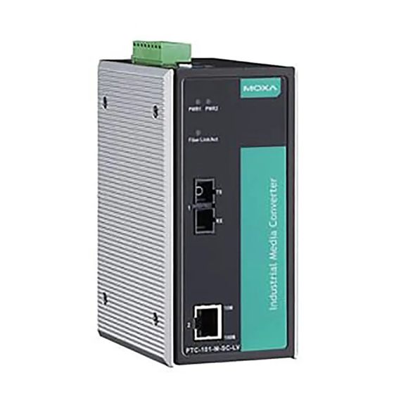
Overview Moxa Industrial Media Converter, which is specially designed for reliable and stable operation in harsh industrial environments, provides industrial grade media conversion between 10/100BaseT(X) and 100BaseFX. PTC-101’s reliable industrial design is excellent for keeping your industrial automation applications running continuously, and comes with a relay output warning alarm to help prevent damages and losses. - Page 3 Panel Layout of PTC-101 Series Top Panel View Grounding screw Terminal block for power input Heat dissipation vents and relay output DIP switch Power input PWR LED Fiber Link/Active LED 100BaseFX Port Front Panel View Front Panel View (PTC-101-M-SC-HV) (PTC-101-M-ST- LV)
-
Page 4: Wiring Requirements
Dimensions (For PTC-101-M-SC-HV. Others are provided by requests.) 15 mm 42.4 mm (1.67 in) 40 mm (1.57 in) (0.59 in) 19 mm 19 mm (0.75 in) 67.4 mm (2.65 in) (0.75 in) 101.4 mm (3.99 in) 101.4 mm (3.99 in) 111.4 mm (4.39 in) 12.06 mm (0.47 in) 123.46 mm (4.86 in) - Page 5 You should also pay attention to the following points: Use separate paths to route wiring for power and devices. If power wiring and device wiring paths must cross, make sure the wires are perpendicular at the intersection point. NOTE: Do not run signal or communications wiring and power wiring in the same wire conduit.
-
Page 6: Communication Connections
ATTENTION Before connecting PTC-101-LV to the DC power inputs, make sure the DC power source voltage is stable. Communication Connections PTC-101 models have one 10/100BaseT(X) Ethernet port, and one 100BaseFX (SC, ST, or LC type connector) fiber port. 10/100BaseT(X) Ethernet Port Connection The 10/100BaseT(X) ports located on PTC-101’s front panel are used to connect to Ethernet-enabled devices. -
Page 7: 100Basefx Ethernet Port Connection
100BaseFX Ethernet Port Connection The concept behind the SC port and cable is quite straightforward. Suppose you are connecting devices I and II. Contrary to electrical signals, optical signals do not require a circuit in order to transmit data. Consequently, one of the optical lines is used to transmit data from device I to device II, and the other optical line is used transmit data from device II to device I, for full-duplex transmission. -
Page 8: Dip Switch Setting
DIP Switch Setting DIP No. Function Auto Negotiation Enable Disable “ON”: Enables “Auto Negotiation” function, the speed and duplex states for each port link segment are automatically configured using the highest performance interoperation mode. “OFF”: Disables “Auto Negotiation” function, the speed and duplex states depend on the manual setting configuration. -
Page 9: Led Indicators
LED Indicators The front panel of Moxa Industrial Media Converter contains several LED indicators. The function of each LED is described in the table below. Color State Description Power is being supplied to power input PWR1 Green PWR1 Power is not being supplied to power input PWR1 Power is being supplied to power input PWR2... - Page 10 Dip Switches: Dip No. Function Auto Negotiation Enable Disable Force TP Speed 100 Mbps 10 Mbps Force TP Duplex Full Duplex Half Duplex Link Fault Pass Throuth Enable Disable Operating Mode Store-and-Forward Pass Through Default DIP settings are all at ON position. Alarm Contact One relay output with current carrying capacity of 1 A @ 24 VDC...
- Page 11 Regulatory Approvals Safety UL 60950-1 FCC Part 15, CISPR (EN55022) class A EN61000-4-2 Edition 1.2: 2001-04 (Level 4) EN61000-4-3: 1995+A1: 2001 IEC 61000-4-3: 2002+A1: 2002 (Level 3) EN61000-4-4: 2004 (Level 4) EN61000-4-5: 2001-04 (Level 4) EN61000-4-6: 2004-11 (Level 3) EN61000-4-8: 2001-03 (Level 5) EN61000-4-11: 2004-03 (Criteria B) Power Automation IEC 61850-3, IEEE 1613...
Need help?
Do you have a question about the PTC-101 Series and is the answer not in the manual?
Questions and answers