Table of Contents
Advertisement
Quick Links
Quick Installation Guide
Moxa Industrial Media Converter
Moxa Americas:
Toll-free: 1-888-669-2872
Tel:
1-714-528-6777
Fax:
1-714-528-6778
Moxa Europe:
Tel:
+49-89-3 70 03 99-0
Fax:
+49-89-3 70 03 99-99
Moxa India:
Tel:
+91-80-4172-9088
Fax:
+91-80-4132-1045
PTC-101
Edition 5.1, November 2017
Technical Support Contact Information
www.moxa.com/support
2017 Moxa Inc. All rights reserved.
Moxa China (Shanghai office):
Toll-free: 800-820-5036
Tel:
+86-21-5258-9955
Fax:
+86-21-5258-5505
Moxa Asia-Pacific:
Tel:
+886-2-8919-1230
Fax:
+886-2-8919-1231
P/N: 1802001016015
*1802001016015*
Advertisement
Table of Contents

Related Manuals for Moxa Technologies PTC-101 Series


Summary of Contents for Moxa Technologies PTC-101 Series
- Page 1 PTC-101 Quick Installation Guide Moxa Industrial Media Converter Edition 5.1, November 2017 Technical Support Contact Information www.moxa.com/support Moxa Americas: Moxa China (Shanghai office): Toll-free: 1-888-669-2872 Toll-free: 800-820-5036 Tel: 1-714-528-6777 Tel: +86-21-5258-9955 Fax: 1-714-528-6778 Fax: +86-21-5258-5505 Moxa Europe: Moxa Asia-Pacific: Tel: +49-89-3 70 03 99-0 Tel: +886-2-8919-1230...
-
Page 2: Package Checklist
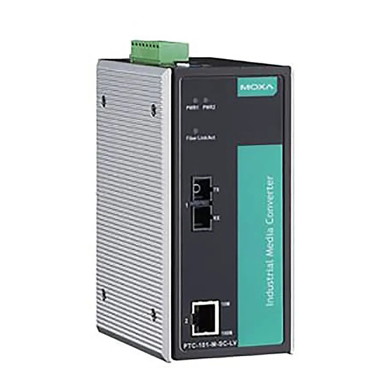
Overview Moxa’s PTC-101 industrial media converters are specially designed for reliable and stable operation in harsh industrial environments, and provide industrial grade media conversion between 10/100BaseT(X) and 100BaseFX. The PTC-101’s reliable industrial design is excellent for keeping your industrial automation applications running continuously, and comes with a relay output warning alarm to help prevent damage to your equipment. - Page 3 Panel Layout of the PTC-101 Series 1. Grounding screw 2. Terminal block for power input 3. Heat dissipation vents and relay output 4. DIP switch 5. Power input PWR LED 6. Fiber Link/Active LED 7. 100BaseFX Port (ST/SC/LC connector) 8. 10/100BaseT(X) 9.
-
Page 4: Wiring Requirements
Dimensions (for the PTC-101-S-SC; other models available by request) Wiring Requirements ATTENTION Safety First! Be sure to disconnect the power cord before installing and/or wiring your Moxa Industrial Media Converter. - 4 -... - Page 5 ATTENTION Safety First! Calculate the maximum possible current in each power wire and common wire. Observe all electrical codes dictating the maximum current allowable for each wire size. If the current goes above the maximum ratings, the wiring could overheat, causing serious damage to your equipment.
-
Page 6: Communication Connections
Wiring the Redundant Power Inputs for the PTC-101-LV series The top five contacts of the 8-contact terminal block connector on the PTC-101-LV’s top panel are used for the PTC-101-LV’s two DC inputs. Top and front views of one of the terminal block connectors are shown here. STEP 1: Insert the negative/positive DC wires into the V-/V+ terminals. - Page 7 RJ45 (8-pin) to RJ45 (8-pin) Straight-Through Cable Wiring RJ45 (8-pin) to RJ45 (8-pin) Cross-Over Cable Wiring 100BaseFX Ethernet Port Connection The concept behind the SC port and cable is quite straightforward. Suppose you are connecting devices I and II. Contrary to electrical signals, optical signals do not require a circuit in order to transmit data.
-
Page 8: Redundant Power Inputs
Redundant Power Inputs For the PTC-101-LV series, both power inputs can be connected simultaneously to live DC power sources. If one power source fails, the other live source acts as a backup, and automatically supplies all of the Moxa Industrial Media Converter’s power needs. DIP Switch Setting DIP No. -
Page 9: Led Indicators
LED Indicators The front panel of the Moxa Industrial Media Converter contains several LED indicators. The function of each LED is described in the table below. Color State Description Power is being supplied to power input PWR1 PWR1 Green Power is not being supplied to power input PWR1 Power is being supplied to power input PWR2... - Page 10 Optical Fiber: 100BaseFX Multi-mode Single-mode Wavelength 1300 nm 1310 nm Max. TX -10 dBm 0 dBm Min. TX -20 dBm -5 dBm RX Sensitivity -32 dBm -34 dBm Link Budget 12 dB 29 dB Typical Distance 5 km 40 km 4 km Saturation -6 dBm...
Need help?
Do you have a question about the PTC-101 Series and is the answer not in the manual?
Questions and answers