
Related Manuals for Moxa Technologies PTC-101-M12


Summary of Contents for Moxa Technologies PTC-101-M12
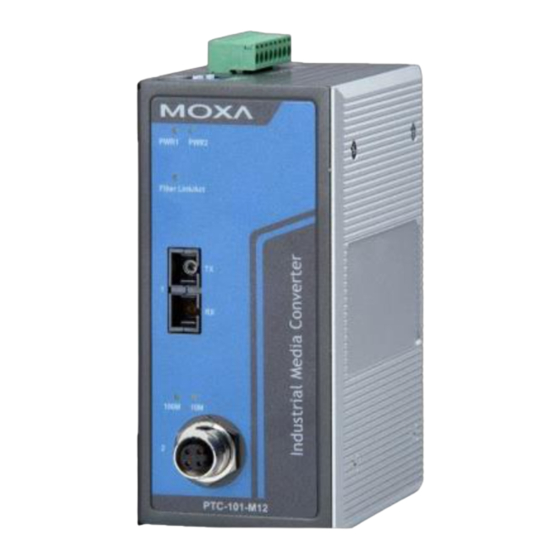
- Page 1 PTC-101-M12 Hardware Installation Guide Moxa Industrial Media Converter Second Edition, January 2013 2013 Moxa Inc. All rights reserved. P/N: 1802001016020...
-
Page 2: Package Checklist
PTC-101-M12 comes with a relay output warning alarm to help prevent damage to your equipment. The PTC-101-M12 has a wide operating temperature range of -40 to 85°C, and is designed to withstand a high degree of vibration and shock. The... -
Page 3: Panel Layouts
Panel Layouts 1. Grounding screw 2. Terminal block for power input 3. Normal Open (NO, COM) / Normal Close (NC, COM) 4. DIP switch 5. Power input PWR LED 6. Fiber Link/Active LED 7. 100BaseFX Port (ST/SC connector) 8. TP port 100 Mbps LED 9. -
Page 4: Wiring Requirements
ATTENTION Safety First! • Be sure to disconnect the power cord before installing and/or wiring your PTC-101-M12. • Calculate the maximum possible current in each power wire and common wire, and observe all electrical codes dictating the maximum current allowable for each wire size. -
Page 5: Grounding The Ptc-101-M12
Wiring the Redundant Power Inputs The top five contacts of the 8-contact terminal block connector on the PTC-101-M12’s top panel are used for the two DC inputs. Top and front views of one of the terminal block connectors are shown here. -
Page 6: Communication Connections
The PTC-101-M12 has one 10/100BaseT(X) Ethernet port, and one 100BaseFX (SC or ST type connector) fiber port. 10/100BaseT(X) Ethernet Port Connection The 10/100BaseT(X) ports located on the PTC-101-M12’s front panel are used to connect to Ethernet-enabled devices. Pinouts for the 10/100BaseT(X) Ports... -
Page 7: 100Basefx Ethernet Port Connection
ST-Port to ST-Port Cable Wiring Redundant Power Inputs The PTC-101-M12 has two power inputs, which can be connected simultaneously to live DC power sources. If one power source fails, the other live source acts as a backup, and automatically supplies all of the PTC-101-M12’s power needs. -
Page 8: Dip Switch Settings
100 Mbps, which is equivalent to full duplex mode. Default DIP settings are all in the ON position. ATTENTION After changing the DIP switch setting, you will need to power off and then power on the PTC-101-M12 to activate the new setting. - 8 -... -
Page 9: Led Indicators
LED Indicators The front panel of the PTC-101-M12 has several LED indicators. The function of each LED is described in the table below. Color State Description Power is being supplied to power input PWR1. PWR1 Green Power is not being supplied to power input PWR1. -
Page 10: Power Requirements
Optical Fiber: 100BaseFX, Single-mode Wavelength 1310 nm Max. TX 0 dBm Min. TX -5 dBm RX Sensitivity -34 dBm Link Budget 29 dB Typical Distance 40 km Saturation -3 dBm * 9/125 μm, 3.5 PS/(nm*km) fiber optic cable Power Requirements Input Voltage 20 to 72 VDC Power Consumption... - Page 11 Technical Support Contact Information www.moxa.com/support Moxa Americas: Moxa China (Shanghai office): Toll-free: 1-888-669-2872 Toll-free: 800-820-5036 Tel: +1-714-528-6777 Tel: +86-21-5258-9955 Fax: +1-714-528-6778 Fax: +86-21-5258-5505 Moxa Europe: Moxa Asia-Pacific: Tel: +49-89-3 70 03 99-0 Tel: +886-2-8919-1230 Fax: +49-89-3 70 03 99-99 Fax: +886-2-8919-1231 - 11 -...
Need help?
Do you have a question about the PTC-101-M12 and is the answer not in the manual?
Questions and answers