Advertisement
Quick Links
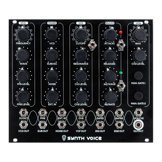
When developing Erica Black Series and Pico Series modules, we accumulated quite a know-how on compact and great sounding designs, and
we decided to share some of those with DIY community. And therefore Erica Synths proudly presents – DIY Synth Voice module! It consists of all
essential blocks for versatile monosynth, and is 100% patchable for even more control options. In order to make the module more compact and
reliable in tuning, it has digital/analogue design. VCO and envelope generators/LFOs are digital, other parts are analogue. Digital parts are designed
arround pre-programmed STM controller, which comes with a kit presoldered on a small contoller board. Chain up several Erica Synths
DIY Synth Voice modules and you have a versatile polysynth!
FEATURES
VCO with 16 waves and manual wave morphing
-1 oct suboscillator
White noise generator
External audio input
Audio Mixer
LP/BP VCF inspired by Black Polivoks VCF
Lin/log ASR envelope generator with looping function
Lin ASR EG/LFO with looping function
9 LFO waves with wave morphing
Tap tempo and LFO sync
LFO frequency multiplication (x2, x4) and division (/2, /4) in sync mode
VCA with bias control
Auto callibration for better 1V/oct tuning
GUIDE ON ASSEMBLY OF THE ERICA SYNTHS DIY SYNTH VOICE
TECHNICAL SPECS
VCO range: ..............................................................................................C1 – C8
Audio output level: ...................................................................................10V ptp
LFO output level: ..................................................................................-5V - +5V
EG output level: ........................................................................................0-+10V
EG1 attack time .................................................................................... 0-500ms
EG1 release time .......................................................................................... 0-2"
EG2 attack time .................................................................................... 0-500ms
EG2 release time .......................................................................................... 0-1"
LFO frequency: ................................................................................ 0,1Hz - 70Hz
VCA attenuation level: ..................................................................................80dB
Panel width: ................................................................................................ 30HP
Module depth: ............................................................................................35mm
Power consumption: ................................................. 82mA@+12V, 50mA@-12V
Advertisement

Related Manuals for Erica Synths Black Series


Summary of Contents for Erica Synths Black Series
- Page 1 When developing Erica Black Series and Pico Series modules, we accumulated quite a know-how on compact and great sounding designs, and we decided to share some of those with DIY community. And therefore Erica Synths proudly presents – DIY Synth Voice module! It consists of all essential blocks for versatile monosynth, and is 100% patchable for even more control options.
- Page 2 GUIDE ON ASSEMBLY OF THE ERICA SYNTHS DIY SYNTH VOICE Here are basic blocks and their connections of Erica Synths Synth Voice!
- Page 3 GUIDE ON ASSEMBLY OF THE ERICA SYNTHS DIY SYNTH VOICE EG2/LFO gives you linear ASR envelope generator or The Mixer is straight forward – set desired VCF has two cutoff CV level attenuators - tap tempo LFO with 16 selectable waveforms. When...
- Page 6 GUIDE ON ASSEMBLY OF THE ERICA SYNTHS DIY SYNTH VOICE Component designators – Control board...
- Page 7 GUIDE ON ASSEMBLY OF THE ERICA SYNTHS DIY SYNTH VOICE Component designators – Main board...
- Page 8 GUIDE ON ASSEMBLY OF THE ERICA SYNTHS DIY SYNTH VOICE Component values – Main board...
- Page 9 GUIDE ON ASSEMBLY OF THE ERICA SYNTHS DIY SYNTH VOICE Component values – Main board...
- Page 10 GUIDE ON ASSEMBLY OF THE ERICA SYNTHS DIY SYNTH VOICE DIY_Synth_Voice_control_v1_1 Erica Synths DIY Synths Voice Controll board Bill of Materials V 1_1 Designator Package Qtty Designation Supplier and ref CERAMIC CAPACITORS C8,C10,C13,C14,C20,C28,C35,C39 C-5mm 8 0.1uF C53,C54 C-5mm 2 68nF...
- Page 11 GUIDE ON ASSEMBLY OF THE ERICA SYNTHS DIY SYNTH VOICE DIY_Synth_Voice_main_v1_1 Erica Synths DIY Synths Voice Mainl board Bill of Materials V 1_1 Designator Package Qtty Designation Supplier and ref CERAMIC CAPACITORS C2,C7,C15,C16,C17,C18,C19,C22,C23,C24,C25, C26,C27,C29,C30,C31,C32,C33,C34,C37,C38,C 40,C43,C48,C51,C65 C-5mm 26 0.1uF C3,C4 C-5mm 2 2.2nF...
- Page 12 GUIDE ON ASSEMBLY OF THE ERICA SYNTHS DIY SYNTH VOICE What you get? The Synth Voice kit comes in three versions: 1) Set of 2 PCBs + MCU board + 2xK140UD12 opamps + mechanical parts (PCB connectors and spacers) 2) Set of 2 PCBs + MCU board + 2xK140UD12 opamps + mechanical parts (PCB connectors, spacers) + panel 3) Full kit, so you do not need to worry about ordering parts.
- Page 13 ASSEMBLY 1. Take precautions with regard to electrostatic discharge (ESD) safety. Handling components should be done in electrostatically safe environment. Use personal and workplace grounding. Any discharge (even a minor one) from body to a component may permanently damage it. 2.
- Page 14 ASSEMBLY 3. There are optional ferrite beads and capacitors for noise generator power supply filtering in order to prevent possible noise getting into PSU circuit. You may omit those and replace ferrite beads with wire jumpers (leave capacitors unpopulated). As our experiments show, the module works fine with wire jumpers.
- Page 15 ASSEMBLY 5. Install also ferrite beads and reverse polarity protection diodes. 6. Now, let’s sort ceramic and film capacitors! Capacitors provided with kit look like this: 15 pF 47 pF 150 pF 22 nF 47 nF 68 nF 100 nF...
- Page 16 ASSEMBLY 7. Populate all cearmic and film capacitors on both PCBs!
- Page 17 ASSEMBLY 8. Insert and solder IC sockets! Pay attention on the orientation key! 9. Install K140UD12 opamps in the VCF circuit! Pay attention on orientation key – it has to fit one on the silkscreen. Use tweezers to align pins of the ICs. Also solder transistors on both PCBs and voltage reference LM4040! Transistors and voltage reference look similar, therefore follow the silkscreen and make sure, you do not mix up NPN 2N3904 and PNP 2N3906 and LM4040!
- Page 18 ASSEMBLY 10. Now let’s figure out, how to install electrolytic capacitors! This is polarized electrolytic capacitor. Minus lug of the capacitor goes to the hole next to the stripe This is non polarized electrolytic capacitor...
- Page 19 ASSEMBLY 11. Solder electrolytic capacitors on the Main board. Pay attention on polarity for polarized capacitors.
- Page 20 ASSEMBLY 13. Solder noise level adjustment trimpot! 12. Solder electrolytic capacitors on the back side of the Controll PCB! Note that non polarized capacitor C1 has to be installed horizontally...
- Page 21 ASSEMBLY 14. Solder PCB connector male pins on the Main PCB! 15. Cut off orientation pins of potentiometers!
- Page 22 ASSEMBLY 17. Turn Controll PCB arround and solder female connector sockets! Also 16. Solder potentiometers on the Controll PCB! solder PSU ribbon cable socket! Mind orientation! Solder fuses (yellow ones). You can replace those by wire jumpers on your own risk.
- Page 23 ASSEMBLY 18. Insert jacks and pushbuttons on the Control PCB, but do not 19. Insert 3 toggle switches and LEDs (pay attention on the orientation – follow solder them yet!! the silkscfreen) in relevant places, but do not solder them yet! 20.
- Page 24 ASSEMBLY 22. Connect all three PCBs! Pay attention on MCU board orientation! 21. Solder male connectors on the small MCU board!
- Page 25 VCO! ENJOY! CONGRATULATIONS! YOU HAVE COMPLETED ERICA SYNTHS If your module doesn’t work, please check the Erica Synths DIY SYNTH VOICE! Synth Voice build thread on Muffwiggler or contact us on the email Now you can connect the module to PSU, and see, what happens. If you haven’t info@ericasynths.lv!
Need help?
Do you have a question about the Black Series and is the answer not in the manual?
Questions and answers