Advertisement
Quick Links
Erica Synths version of the Polivoks VCO uses the core of the original Polivoks VCO, and DIY kit, as all Erica Synths Polivoks modules, comes with a set of the
original Russian ICs and transistors.
Same time, there are plenty of changes in the schematics. We:
1) changed CVs to eurorack standard 1V/Oct (original has inverted CVs)
2) made all CV ins buffered in order to eliminate crosstalk and undesired detune (very few DIY kit producers buffer CV ins - mostly they are just summed on
resistors)
3) made optional adjustments to output signal amplitudes and offsets - you can have the original output signals (they are totally different waveform to
waveform) or make them standard 10Vptp
4) original Polivoks has interesting peak in the triangle waveform - we introduced optional filter to eliminate it or leave as it is
5) we significantly updated pulse wave circuit and introduced PWM - it sounds insanely great!
GUIDE ON ASSEMBLY OF THE ERICA SYNTHS SUPER-ENHANCED POLIVOKS VCO
Advertisement

Subscribe to Our Youtube Channel
Related Manuals for Erica Synths POLIVOKS VCO


Summary of Contents for Erica Synths POLIVOKS VCO
- Page 1 GUIDE ON ASSEMBLY OF THE ERICA SYNTHS SUPER-ENHANCED POLIVOKS VCO Erica Synths version of the Polivoks VCO uses the core of the original Polivoks VCO, and DIY kit, as all Erica Synths Polivoks modules, comes with a set of the original Russian ICs and transistors.
- Page 4 PLEASE FOLLOW INSTRUCTIONS BELOW TO COMPLETE THE MODULE SUCCESSFULLY!
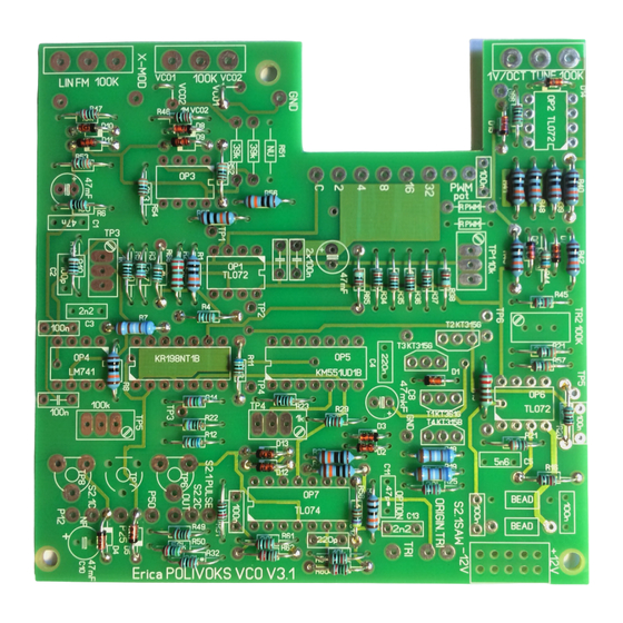
- Page 5 Erica Synths Polivoks VCO PCB is configurable for both VCOs. As the first step use wire jumpers to select the VCO, you are about to build. Note that R47 is 10k for VCO1 and 1M for VCO2.
- Page 6 – you will need them later. NB! The original Polivoks trian- AND R3 HAS TO BE 1K. IF YOU DO NOT DO SO, YOU WILL NOT BE ABLE TO gle waveform has a sharp spike. Erica Synths Polivoks VCO version can TUNE THE VCO.
- Page 7 Solder IC sockets and trimpots. Solder OP2 – it has to be soldered Solder transistors! See the picture below that helps to identify the directly without the socket. Solder PSU socket. transistors. KT315 are NPN transistors, KT361 is PNP transistor. Colors of cases may vary, but the main thing is that KT361 has cyrillic letter G in the middle of the case.
- Page 8 Soviet transistors (KT315 and KT361) are sensitive to light, including infrared. If you do not intend to tune the VCO in the darkness, it’s time for real DIY challenge! We will use the copper sheet included in the kit to make the shield for transistors. a.
- Page 9 Solder potentiometers Wash the PCB to eliminate the flux Insert ICs. Mind the orientation. Install jacks and switches (if you are using rotary switches provided with the full kit, use special washers to configure them to 5 and 6 positions correspondingly) in the front panel.
- Page 10 ERICA SYNTHS POLIVOKS VCO WIRING 1V/OCT OCTAVE X-MOD IN 20 K LIN FM IN OUTPUT PWM IN...
-
Page 11: Tuning The Oscillator
TUNING THE OSCILLATOR Connect a precise frequency meter to the VCO module output. Apply 5.00V to CV input. You can use a voltage divider made up of two resistors, connected to the same +12V supply and GND, providing the middle Ensure all components are placed correctly and soldered well. - Page 12 Roland, ARP, Sequential Circuits or Moog analog synthesizer compatibility. tors: 18k and two 10k. 18k is at the lowermost (connected to ground) or uppermost (connected to OCTAVE_TUNE) position. Points between these Select PWM 50 waveform. resistors serve as additional octave positions, two at each side of the range, Ensure panel that both modulation pots are set to minimum.
Need help?
Do you have a question about the POLIVOKS VCO and is the answer not in the manual?
Questions and answers