Erica Synths Black Sequencer, Black Series Manual
- Manual on assembly (25 pages) ,
- Manual (2 pages) ,
- Quick start manual (2 pages)
Advertisement
Introduction
The Erica Black Series includes high-end, unique functionality and superior quality modules. Only the best, highest quality components are used and all inputs and outputs are protected against undesired overvoltage. When designing the Black Series, we included superior design and usability. Big knobs have been assigned for key functions of the module, which makes the Black Series ideal for live performances. Enjoy! The Erica Synths Black Sequencer takes classical modular sequencing to the next level by adding tons of features required for contemporary modular synthesisers. The Black Sequencer features 4 channels with CV, gate and modulation outputs, up to 64 step sequences that can be chained into longer ones, independent track time divisions, multiplications and lengths. It includes CV and Gate recording, a built-in quantiser, a MIDI in/out and many other features essential for composing and performing electronic and experimental music. Even though it provides many programmable parameters per step, it's intuitive, easy and straight-forward to use, and we believe that it will become a master controller for many modular setups.
FEATURES

- 4 CV/GATE/Modulation tracks
- CV/GATE/MOD recording
- MIDI IN and MIDI OUT
- Clock and Reset In/Out
- 16 encoders for easy data input
- Up to 64 steps per pattern
- Song mode
- Note, Glide, Gate length and Modulation adjustment per step
- Probability, repeats and ratcheting per step
- Microtonal tuning
- Adjustable shuffle per track
- Timing divisions/multiplications per track
- Built in quantiser
- Random pattern generator
- 16 banks of 16 pattern memory
- SD card slot for backup and firmware updates
SPECIFICATIONS
- Power consumption: +145mA, -25mA
- Module width: 42HP
- Module depth: 25mm
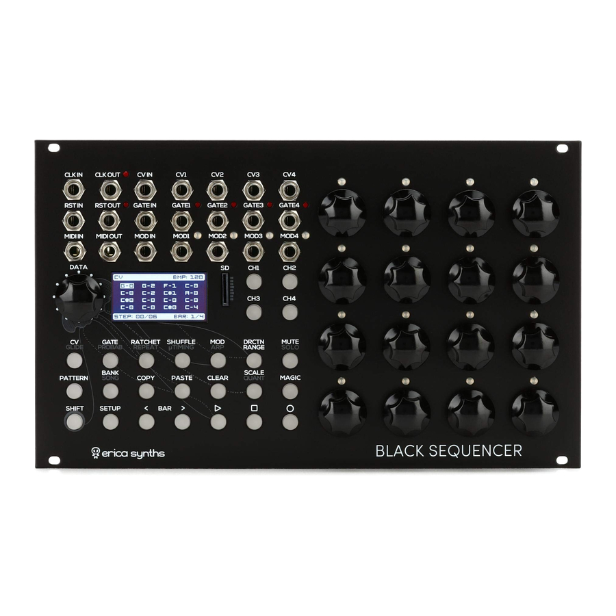
THE INTERFACE

THE BLACK SEQUENCER CONSISTS OF 5 MAJOR PARTS:
- Inputs and Outputs. The Black Sequencer has 4 CV outputs, 4 Gate outputs, 4 configurable Modulation outputs, a configurable CV, Gate and Modulation inputs, configurable Clock input and output, configurable Reset input and output and configurable MIDI input and output.
- Encoders with pushbuttons for per-step parameter adjustment and setting values for specific menus. In menus where the encoders set parameters they light up in orange colour.
- Channel selection buttons – you can select one channel at a time and then adjust the parameters for it.
- Function buttons – in order to ensure easy and swift access to all the functions of the sequencer, there's one button per function and almost no menu diving. Some buttons have dual functions, and the second function (gray silkscreen) can be accessed by holding the SHIFT button.
- The Data encoder provides access to the master settings (e.g BPM, master glide, etc), the OLED screen indicates per step and master settings for the module, and the SD card stores saved patterns. When opening various menus, the setting values appear on the OLED. There are small "hints" under the values that point to the control on the sequencer that adjusts the selected value.
OPERATION
The Black Sequencer features four CHANNELS (CH1 – CH4) – each outputs CV, Gate and Modulation signals, and each channel has configurable TRACK length from 2 to 64 steps, and all 4 tracks are played back simultaneously. All 4 CHANNELS are saved in PATTERNS. A set of 16 PATTERNS is saved in a BANK. A set of 16 banks of 16 patterns is saved in a PROJECT and is stored on the SD card in BANKS of 16 PATTERNS. You can also design a SONG – a series of PATTERNS within one BANK. In order to select a BANK, push and hold the BANK button and push one of the 16 encoders. The same goes for PATTERNS.
MASTER SETTINGS
 | Push the PLAY button! The sequencer will start to advance through the steps in the pattern. Pushing the PLAY button again will PAUSE the sequencer – it will freeze on the current step. Pushing the STOP button will reset the sequence to the first step. Whenever you make changes in the sequence, the RECORD button will start to blink. Push and hold the SHIFT button and push the RECORD button to save the changes in the pattern! |
 | Start with setting the master BPM! Simply rotate the DATA encoder and set the master BPM! The OLED will indicate the master BPM. You can also push and hold the SHIFT button and rotate the DATA encoder to change the BPM for 10 BPM at one rotation. The master screen will always indicate the selected function, the currently active step and the currently active bar. |
 | Each channel has configurable divisions and multiplications of the master BPM! Push one of the CH1 – CH4 buttons to select the channel thet you wish to configure! Push the SCALE button and the SCALE screen will appear. Rotate the DATA encoder to set the division for the master clock. Push and hold the SHIFT button and rotate the DATA encoder to adjust the BPM, if needed. The OLED will indicate the division, and "hint" [DATA] appers under the SCALE setting. This means that the DATA encoder is controlling the SCALE setting, and the SHIFT+DATA encoder sets the BPM. Use the second STEP encoder to adjust the MASTER TRACK LENGTH - this defines number of steps after which the current pattern will advance to the next one, when patterns are switched or in the SONG MODE. The Master Track Length can be 1 to 64 long. |
 | In order to set the PLAY DIRECTION per channel, select a channel from CH1-CH4 and push the DRCTN/RANGE button! The DIRECTION/RANGE screen will appear, showing the current DIRECTION, the current RANGE of steps and the visualization of the active steps divided in to 4 bars. "Hints" below the settings hint the relevant controls. Rotate the DATA encoder to select the play direction. The available play directions are: Forward, Backward, Ping- Pong, Ping-Pong with repeats on the first and the last step, Snake, Snake2 with repeats on the first and the last steps and Random. The default play mode for the empty pattern is Forward. |
 | Rotate the first step encoder to set the first step of the pattern and rotate the second step encoder to set the last step of the pattern. If you are designing pattern of up to 16 steps, for the last step of the pattern you can simply push one of step encoders, and for the first step push and hold the SHIFT button and push one of step encoders. Rotate the third step encoder to move the selected steps along the step grid. For patterns longer than 16 steps, you can activate the BAR FOLLOW function, so that the bar display changes automatically, when the sequencer advances to the next bar. In order to engage the bar follow function, push and hold the SETUP button and push the BAR> button; to disengage it – use the SHIFT + <BAR combination. |
 | When designing a performance with several tracks, useful feature is a TRACK OVERVIEW screen. Push and hold the SHIFT button and push the DRCTN/RANGE button, and the OLED will show all four tracks in one screen. Here you can see play mode, all active steps and time divisions for each pattern. Rotate the first step encoder to alter Play Mode, the second and the third step encoders to change the first and the last steps of the pattern and the fourth step encoder to alter the time division. The first row of step encoders alters parameters of the first track, the second row – of the second track, etc. Use <BAR> buttons to navigate through bars, if you have longer than 16 steps patterns. |
DESIGNING A CV TRACK
 | Start with the quantization settings per channel! Select a channel from CH1-CH4, push and hold the SHIFT button and push the QUANT button! The QUANTIZATION menu will appear on the OLED. Rotate the DATA encoder to select one of the preset quantized scales, and the scale is automatically applied. Push one of the first 12 step encoders to select a root note for the sequence! You can also choose the microtonal note input – steps are not tied to the specific musical scale or even to notes. To do so, select NONE in the SCALE menu. In this case, the step encoders will move along a grid of cents (see NOTE ENTER below). |
 | When in the QUANT menu, you can design your own scales. To do so, push the DATA encoder and the scale menu will appear on the screen. You can design a NEW scale, EDIT one of the previously designed scales, DELETE the scale or CANCEL the action. |
 | Rotate the DATA encoder and make your selection by pushing the encoder! If you choose to design a NEW scale, a new scale design screen will appear. Now you can enter notes in the scale by pushing the first 12 encoders that correspond to the notes. |
 | For microtonal scales, rotate the relevant encoder clockwise to increase the tune for up to 50 cents and counterclockwise to decrease it for up to 50 cents. The OLED will indicate microtonal changes next to the relevant note in the scale. Once done, name the scale: rotate the DATA encoder to navigate through the characters in the scale name below and rotate the first step encoder to alter the selected character! Once you are satisfied, push the DATA encoder to confirm! To exit, push any function knob! |
 | Now, let's set the NOTES per step! Select a channel from CH1-CH4 and push the CV button! The default notes are CO, but you can select your preferred default notes in the SETUP menu. Now you can rotate any of the 16 encoders to set the notes per step. Note of the currently adjusted steps will appear in the pop-up screen on the OLED. The OLED will indicate a grid of 16 notes. You can navigate through sets of 16 steps using the <BAR> buttons. You will have access to the notes within a selected musical scale, set in the QUANT menu in advance. By pushing and holding the SHIFT button and rotating the step encoders, you will advance through octaves instead of semitones. |
 | If the scale NONE is selected in a QUANT menu, the step encoders navigate along the grid of cents, and you can enter microtonal patterns. If you wish to navigate through notes in this setting, push and hold the SHIFT button and rotate the relevant step encoder. When entering notes, you can preview the notes per step by listening to the tune of the VCO – push and hold the CV button and push one of the step encoders. The relevant note will be frozen, while the sequencer is running. This is a nice feature during a performance as well. In the same way you can preview the notes, when the sequencer is stopped. |
 | You can also adjust the MASTER GLIDE and GLIDE PER STEP! To do so, select a channel from CH1-CH4, push and hold the SHIFT button and push the CV/GLIDE button! Adjust the MASTER GLIDE from 0-2" by rotating the DATA encoder. Rotate any of the 16 encoders to set the GLIDE PER STEP time. The per step glide time is linked to the gate length and the BPM. You can select the default glide time in the SETUP menu. |
 | A nice feature is the ARPEGGIATOR PER STEP – it applies quick arpeggios within the step! To apply the arpeggiation, select a channel from CH1-CH4, push and hold the SHIFT button and push the MOD/ARP button! Now rotate any of the 16 encoders to set the arpeggiator scale – the sequencer comes with several built in scales. NB! The arpeggiator will work only with GATE RATCHETING. Please, refer to the manual below! Also nice trick is to set the tracks division for example to 1/4 and length to just 4 steps and add 8 ratchets to each of the steps and then apply arpeggiator per step! |
DESIGNING A GATE TRACK
 | Now, let's set the GATE LENGTH per step! Select a channel from CH1-CH4 and push the GATE button! Now you can rotate any of the 16 encoders to set the gate length per step. The default gate length is 50%, but you can select your preferred default gate length in the SETUP menu. There are 10 discrete gate length settings, where 0 is gate off, and 10 is full gate – the step is merged with the next one. The gate length of the currently adjusted step will appear in the pop-up screen on the OLED. The OLED will indicate a grid of 16 bars indicating the gate length for each step. You can navigate through sets of 16 steps using the <BAR> buttons. |
 | Pushing the encoders while in GATE page offers multiple functions:
|
ADDING DYNAMICS
 | For a more dynamic performance, you can assign GATE PROBABILITY per step. Meaning that each step will be played back at specified occasions; otherwise the gate length will be O. To do so, select a channel from CH1- CH4, push and hold the SHIFT button and push the GATE/ PROBAB button! Rotate any of the 16 encoders to set the GATE PROBABILITY. If you rotate the encoder counter clockwise, you have access to fractions: ⅛, 1⁄7, 1⁄6, 1⁄5, 1⁄4, 1⁄3, 1⁄2, 2⁄3, 3⁄4, 7⁄8. ¼ means, that the step is being played one time out of four, as the sequencer advances through the selected step. If you rotate the encoder clockwise, you have access to probabilities: 10%, 25%, 50%, 75% and 90%. 75% means that the step will be played back randomly on 75% of occasions, when the sequence advances through the selected step. The step grid on the OLED will indicate the probability settings. |
 | For a more dynamic performance, you can also set RACHETING per step, meaning that each gate will be played back multiple times in the selected step length. To do so, select a channel from CH1-CH4 and push the RATCHET button! Rotate any of the 16 encoders to set the RATCHET rate: 2, 3, 4, 5, 6, 7, 8. The step grid on the OLED will indicate the ratchet settings. NB! Ratchet works great together with the per step ARP feature! |
 | For more interesting sequences, you may want to use GATE REPEAT per step. Meaning that each step will be played several times at the same CV, Gate and Modulation settings. To do so, select a channel from CH1-CH4, push and hold the SHIFT button and push the RATCHET/REPEAT button! Rotate any of the 16 encoders to set the GATE REPEAT rate: 2,3,4,5,6,7,8. The step grid on the OLED will indicate the gate repeat settings. |
 | To animate your performance, you can add SHUFFLE to the track, meaning that some gates will be set slightly offbeat. To do so, select a channel from CH1-CH4 and push the SHUFFLE button! Rotate the DATA encoder and set the desired shuffle amount for the track. You can also manually design the shuffle pattern. To do so, manipulate the first four step encoders: pushing the encoder will turn the shuffle of the step on/off (a small square indicates that a shuffle will not apply to the selected step), if the shuffle is applied, by turning the relevant encoder you can define, if the shuffle microtiming is applied to positive (+) or negative (-) direction. Your 4-step pattern will be replicated on the all steps of the track. |
 | For even more nuanced timing adjustments, you can apply MICROTIMING per step, meaning each step will be played slightly offbeat at a specified time. To apply microtiming, select a channel from CH1-CH4, push and hold the SHIFT button and push the SHUFFLE/TIMING button! Rotate any of the 16 encoders to set the microtiming per step! The step grid on the OLED will indicate the microtiming settings. If the SHUFFLE is applied to the track, it will automatically appear in the microtiming screen. |
DESIGNING A MODULATION TRACK
 | Each channel of the Black Sequencer has a dedicated MODULATION OUTPUT. This means that you can design a modulation track for controlling filters and other modules. But, modulation outputs are not limited to step by step voltages only. Modulation outputs can be configured as follows:
|
 | Note that each channel can have an individual configuration. In order to configure the modulation output, select a channel from CH1-CH4 and push and hold the SETUP button and push the MOD button. Rotate the DATA first step encoder to set the desired configuration! To exit the configuration screen, simply push the MOD button again! |
 | For example, in order to configure the modulation output for the STEPPED CVs, push and hold the SETUP button and push the MOD button. The configuration screen will appear. Rotate the DATA first encoder to select the CV. Push the MOD button again to return to the per step modulations settings page. |
 | In the STEPPED MODULATION (CV) mode, rotate any of the 16 encoders to set the desired output voltage. Maximum output voltage range is from -10V - +10V; you can customize the range in the settings menu. The step grid on the OLED will indicate modulation voltage settings. |
 | In the CV NOTE mode the stepped voltages are linked to the notes and you can basically design another CV track. For example, if your VCF tracks 1V/oct, you can mimic keyboard tracking. Note that in this mode, you also have access to negative voltages that are linked to notes. |
 | In the DECAY ENVELOPE mode (the decay starts immediately after the gate is on and the gate length is ignored) rotate any of the 16 encoders to set the desired Decay time per step. The attack time is fixed, and it's instantaneous while the decay time is linked to the BPM – the minimum is O", but the maximum is always equal to the time of the two steps in the sequence playback. If the ratchet is applied to the step, the max release release time is equal to two ratchetted substeps in the gate. The step grid on the OLED will indicate the decay envelope time settings. |
 | In ASR ENVELOPE mode (release starts after the gate is off, and the gate length is taken into account), rotate any of the 16 encoders to set the desired Attack-Sustain-Release envelope release time. The attack time is fixed, and it's instantaneous, the sustain level is 10V, and release time is linked to the BPM – the minimum is O", but the maximum is always equal to the time of two steps in the sequence playback. If ratchet is applied to the step, the max release time is equal to two ratchetted substeps in the gate. The step grid on the OLED will indicate the decay envelope time settings. |
 | In the ADSR ENVELOPE mode, encoders 1-4 become the Attack, Decay, Release time and Sustain level settings for each channel. In the ADSR ENVELOPE mode the maximum Attack and Decay time is equal to the Gate length, the maximum Release time is linked to the BPM – the minimum is O", but the maximum is always equal to the time of two steps in the sequence playback. If the ratchet is applied to the step, the max release time is equal to two ratchetted substeps in the gate. The maximum Sustain level is +5 or +10V depending on the configuration. |
 | In LFO mode (the MOD output becomes synced or free running LFO), encoders 1-4 become LFO parameter settings. Encoder 1 becomes the LFO frequency control (in sync mode it will set LFO frequency as divisions or multiplications of the BPM), encoder 2 sets the waveshape, encoder 3 – the LFO signal level (-5V - +5V max) and encoder 4 turns LFO Synchronization to BPM ON/OFF. The OLED will indicate LFO settings. |
 | In the STEPPED LFO mode, the LFO with the frequency linked to the BPM is available on the MOD outputs, and you can select the LFO waveform per step. The available waveforms are: sine, triangle, saw up, saw down and square. |
 | In the TRIGGER mode, the modulation output will output 5ms +5V triggers, ideal for triggering drum modules or other events in your modular system. Push encoders 1-16 to engage the triggers at relevant steps. For longer than 16 step patterns, use the <BAR> buttons to navigate to the next pages of 16 steps. The step grid on the OLED will indicate the active triggers. |
MANAGING PATTERNS, BANKS AND SONGS
The memory of the sequencer is structured in several layers: PROJECTS, BANKS, PATTERNS and TRACKS. A PROJECT is saved on the SD card and contains 16 BANKS of 16 PATTERNS, each PATTERN consisting of 4 TRACKS (CH1-CH4) with all parameter settings. Furthermore, each BANK can contain up to 16 SONGS – an array of PATTERNS within a BANK.

 | You can SAVE patterns at any moment. All the alterations that you make in the pattern are recorded in the temporary memory of the sequencer and will be lost if you switch to another pattern or turn off the unit. A blinking RECORD button indicates that the information has not been saved. To SAVE the pattern information, just push and hold the SHIFT button and push the RECORD button, and all settings within the pattern (all four tracks CH1-CH4) will be saved in the selected BANK and PATTERN. |
 | Push and hold the SHIFT button and push the PATTERN button to access the PROJECTS (a set of 16 BANKS of PATTERNS stored on the SD card) menu. Rotate the DATA encoder to select the project and push to confirm. |
 | Push the BANK button to select the BANK! The OLED shows the grid of 16 BANKS and the numbers in the BANKS indicate the number of patterns saved in each bank (3 and 2 correspondingly in the example shown on the OLED). The LEDs above the step encoders indicate BANKS with patterns – the orange LED means, the BANK holds some PATTERNS, while the green means the BANK is selected. |
 | Push the PATTERN button to select a PATTERN within a BANK selected in a previous step! The OLED shows the currently selected PATTERN and the BANK number below. |
 | In order to select the next PATTERN, simply push one of the step encoders for the pattern you wish to initiate, and the NEXT PATTERN icon will appear on the OLED. The sequencer will advance to the next PATTERN as soon the current one is complete (this is defined by the Master Track Length setting in the SCALE menu). If you wish to advance to the next PATTERN INSTANTLY, push and hold the SHIFT button and push one of the step encoders for the pattern that you want to initiate. The LEDs above the step encoders indicate the PATTERNS that have been saved in the memory within a current BANK – the red LED means the PATTERN is saved, green means the PATTERN is selected, but it's empty, while the orange – the pattern is selected, and is saved in the memory. Nice performance-oriented feature is PATTERN LINKING. Push and hold the PATTERN button and push several step encoders that contain patterns buttons (you can push the same pattern repeatedly, as well). All selected patterns will play sequentially in the loop. Push any step encoder to select another pattern and terminate the chain of patterns. |
 | You can design a SONG – a chain of PATTERNS from one BANK, played back sequentially. In order to enter SONG design mode, push and hold the SHIFT button and push the BANK/SONG button. Now push one of 16 step encoders to LOAD a SONG or open a NEW SONG design menu, if the SONG slot is empty. In total, 16 SONGS are available per BANK, each SONG can contain up to 64 patterns, and each pattern in the chain can be repeated up to 32 times. Green step LEDs will indicate saved songs in 4x4 step encoder pattern. |
 | If you choose to design a NEW SONG, simply push the step encoders to design a chain of PATTERNS. The red LEDs above the step encoders will indicate saved PATTERNS that are available for a SONG design. You can push the same encoder several times to repeat the PATTERN. The OLED will show the PATTERNS within the SONG. You can also use the DATA encoder to navigate through chain of PATTERNS and alter or insert some patterns in a SONG. To insert the pattern, navigate to the slot in-between patterns and push the step encoder of the PATTERN, you wish to insert, to modify/replace the PATTERN, navigate to the PATTERN in a chain and push the step encoder of the PATTERN, you want insert instead of existing PATTERN. You can also rotate the the first step encoder to alter the PATTERN number and the second step encoder to alter the number of repeats. You can DELETE the pattern in a chain by pushing the CLEAR button. If you wish to delete entire pattern chain, push and hold the SHIFT button and push the CLEAR button. To SAVE the SONG, push and hold the SHIFT button and push the RECORD button. If you choose to DELETE the SONG, simply push and hold the CLEAR button and push the relevant step encoder. NB! If the song is playing (a sequencer is running) pushing SFIFT+SONG will get to the currently playing song. If you wish to design a NEW SONG, make sure, a sequencer is stopped. Please note that the SONG mode is a performance oriented feature, and it's not intended to alter patterns while the SONG is playing. |
PARAMETER CLEAR, COPY PASTE
 | You can CLEAR all track information or certain parts/steps/ settings. In order to CLEAR ALL track information, push and hold the CLEAR button and push the track button from CH1-CH4 for the track that you want to clear. For example, pushing CLEAR + CH1, all the information in track 1 will be reset to default settings (eg. all CVs to C0, and all gates to 50%, all modulation voltages to 0V). In order to clear an entire PATTERN, open the PATTERN menu, push and hold the CLEAR button and push the relevant step encoder. |
 | In order to CLEAR all the information in certain steps, select a track from CH1-CH4, push and hold both CLEAR and SHIFT buttons and by pushing encoders 1-16, select the step that you wish to clear. You can also clear series of steps by pushing the first and the last encoder in the series. The step grid in the popup screen on the OLED will indicate which steps are cleared. |
 | In order to CLEAR CVs for a specific track (CH1, for example) only, push the CV button to select the CV menu, then push and hold the CLEAR button and push the CH1 button. All CV information for CH1 will be reset to the default setting (C0, for example). If you want to clear GLIDE settings, select the GLIDE mode (SHIFT+CV/GLIDE), push and hold the CLEAR button and push the CH1 button. All glide information for CH1 will be reset to O". In the same way, you can CLEAR GLIDE information for specific steps. To do so, instead of pushing the CH1 button, push the step encoders for the steps that you wish to clear. |
 | The same goes for clearing GATES, PROBABILITIES, RATCHETS, etc. for a specific track (CH1, for example). In order to clear GATES, push the GATE button to select the GATE menu, then push and hold the CLEAR button and push the CH1 button. All GATE information for CH1 will be reset to the default setting (50%, for example). In order to CLEAR information for specific steps, instead of pushing the CH1 button, push the step encoders for the steps that you wish to clear. |
 | You can COPY and later paste all track information from CH1 – CH4 or all settings in certain steps. In order to COPY ALL track information, push and hold the COPY button and push a track button from CH1 – CH4 for the track that you want to copy. For example, to copy all information in track 1, push COPY+CH1. In order to COPY an entire PATTERN, open the PATTERN menu, push and hold the COPY button and push the relevant step encoder. |
 | In order to COPY all information in certain steps, select a track from CH1 – CH4, push and hold the COPY button and by pushing encoders 1-16, select the step that you wish to copy. You can also copy series of steps by pushing the first and the last encoder in the series. The step grid in the popup screen on the OLED will indicate which steps have been copied. |
 | In order to PASTE all the information from a specific track to another track (for example, if you copied information in CH1 and want to paste it to CH2), push and hold the PASTE button and push the CH2 button. All information from CH1 will be pasted to CH2. If you have copied a series of steps, not an entire pattern, only the steps that have been copied will be pasted. For example, if you are happy with how the first 4 steps of the sequence sound, you can paste them into steps 9 - 12 simply by pushing and holding paste, and pushing step encoder 9. In order to PASTE an entire PATTERN, open the PATTERN menu, push and hold the PASTE button and push the step encoder for the paste destination. |
 | You can also PASTE the specific settings from the channel, like CVs, GATES, PROBABILITIES, RATCHETS, etc. To PASTE CV settings only, select the CV mode (CV button is ON), push and hold the PASTE button. Then select a destination – push one of the encoders to paste a step/several steps or push a channel button to paste CV settings to the same steps in another channel. The same goes for other parameters. For example, for glide settings, select the glide mode (SHIFT+CV/GLIDE) and push and hold PASTE and select a destination. |
DURING THE PERFORMANCE
 | You can MUTE channels during a performance. Push the MUTE button and push one or several CH buttons to mute relevant the channels. Mute means – all GATES and MODULATIONS will be turned off, but the sequencer will continue running and output CVs You can SOLO the channel. Push and hold SHIFT and push the MUTE/SOLO button. Then select a channel from CH1- CH2 that you wish to play solo. Gates and Modulations for all other channels will be turned off. |
 | The MAGIC button does magic – it randomizes all track information or parameter information within preset scales. In order to randomize all parameters in the channel, push and hold the MAGIC button and push one of the CH1-CH4 buttons! All selected (please, refer to the MAGIC SETUP) parameters for the selected channel will be randomized. In order to randomize a specific parameter, a CV for channel 1, for example, push channel button CH1, then push and hold the MAGIC button and push the CV button. The CVs for channel 1 will be randomized within a preset musical scale, while the glide, gate and modulation information will remain the same. The same goes for Gates, Modulations, etc. For example, if you wish to "Magic" GLIDE, push and hold the MAGIC button, then push the SHIFT button and push CV/GLIDE button. |
 | You can adjust randomization settings, for example the octave range for CV randomization. To do so, push and hold the SETUP button and push the MAGIC button. Use the DATA encoder to navigate through parameters and the first and the second encoders to adjust settings. Here you also can define, what parameters will be randomized, when one of CH1 - CH4 buttons is pressed. To do so, rotate the DATA encoder to navigate through the list of parameters and push it to select a specific parameter. A filled dot next to the parameter means this parameter will be randomized. In the example to the left CVs, Gates and Ratchets are randomized, while Glide, Probability and Repeat stay unaltered. Nice extra feature is Gate State (STATE) randomization – it randomly turns gates ON or OFF thus altering the sequence without changing other parameters. |
SETTINGS MENU
The SETUP menu provides basic information about the device status, as well as providing access to default settings and the calibration of the sequencer. Rotate the DATA encoder to navigate through the setup icons and push it to confirm the selection!

 | The Info menu indicates information about the firmware and bootloader versions. Also, you can perform a manual firmware update/module reboot here. Push and hold the SHIFT button and push the first step encored, and the sequencer will reboot. |
 | In Display settings menu you can:
|
 | in General settings menu you can activate several features that affect overall functionality of the sequencer:
|
 | In the DEFAULT Settings menu, you can define the default parameters of the sequencer when the new empty sequence is activated, or the CLEAR function is performed. You can:
|
 | In the Input and Output CALIBRATION menu, you can calibrate the sequencer to work best in your system – you can even calibrate the CV outputs to work best with specific VCOs. In order to perform calibration push the DATA encoder to enter the CALIBRATION mode and follow the instructions on the OLED. NB! The sequencer comes factory calibrated 1V/oct, so, if your VCOs are perfectly tuned 1V/oct, you do not need extra calibration. |
 | In the MIDI Settings menu, you can assign MIDI message values per channel. First push the Channel button (CH1-CH4) to select the channel! Use the FIRST STEP ENCODER to access inputs and outputs in the horizontal menu (CV OUT, MOD OUT, CV IN and MOD IN) and the DATA encoder to navigate through parameters vertically! Then use the SECOND STEP ENCODER to alter values for the parameter! In V1.0 firmware the MIDI settings are disabled. |
 | In the CLOCK setup menu you can select the CLOCK source: INTERNAL - the sequencer runs from the internal clock, and you can set the BPM as described above, EXTERNAL – use this setting, if you use a master clock from another source. In this case you need to patch a clock source into CLK IN and the the sequencer will indicate a BPM of the master clock, as well as "clock quality" – how accurate an external clock source is. The closer it is to 0, the more accurate the clock source is (it does not have undesired jitter or shuffle). By default the sequencer accepts 4ppq clock. MIDI – in this setting the sequencer uses MIDI clock from an external source, patched in MIDI IN socket. Also here you can monitor the clock quality. By default the sequencer accepts a standard 24ppq MIDI clock, In order to switch between clock sources, rotate the DATA encoder, and the OLED will indicate a selected clock source. |
 | In IN/OUT menu you can configure input and Output settings. In the V1.0 firmware you can set the ppq for the CLK OUT. A default setting is 4ppq, but you can change it by rotating the first step encoder. |
FIRMWARE UPDATE
 | In order to update the firmware of the Black Sequencer, power off your modular case, remove the SD card from the Sequencer, copy the latest firmware file on the root directory of the SD card and insert the SD card back in the sequencer! Turn on the power on your modular case, and the Sequencer will automatically detect the latest firmware, erase the old one, and upload the new one. Your saved patterns will remain unchanged, and you'll be able to use them with the latest firmware. To backup or exchange your patterns just copy the PROJECTS folder to your computer. |
SAFETY INSTRUCTIONS
Please follow the instructions for the use of the Erica Synths module below, because only this will guarantee the proper operation of the module and ensure your warranty from Erica Synths.
 | Water is lethal for most electric devices, unless they are waterproof. This Erica Synths module is NOT intended for use in a humid or wet environment. No liquids or other conducting substances must be allowed to get into the module. Should this happen, the module should be disconnected from mains power immediately, dried, examined and cleaned by a qualified technician. |
 | Do not expose the module to temperatures above +50°C or below -20°C. If you have transported the module in extreme low temperatures, leave it at room temperature for an hour before plugging it in. |
 | Transport the instrument carefully and never let it drop or fall over. Our warranty does not apply to modules with visual damage. |
 | The module must be shipped in the original packaging only. Any module shipped to us for return, exchange and/or warranty repair must be in its original packaging. All other deliveries will be rejected and returned to you. Ensure that you keep the original packaging and technical documentation. |
 | This device complies with EU guidelines and is manufactured RoHS conforming, without the use of lead, mercury, cadmium or chrome. Nevertheless, this device is considered to be special waste and disposal in household waste is not recommended. |
Documents / Resources
References
Download manual
Here you can download full pdf version of manual, it may contain additional safety instructions, warranty information, FCC rules, etc.
Advertisement


Need help?
Do you have a question about the Black Series and is the answer not in the manual?
Questions and answers