Table of Contents
Advertisement
Advertisement
Table of Contents

Related Manuals for JRC Handy Search NJJ-95B


Summary of Contents for JRC Handy Search NJJ-95B
- Page 1 NJJ−95B Handy Search Instruction Manual...
- Page 2 Preface Thank you very much for purchasing this JRC NJJ-95B Handy Search The NJJ-95B RC radar nondestructively locates, detects, and displays the depths and positions of reinforcing steel bars in reinforced concrete structures. Before attempting to operate the NJJ-95B, please read through this instruction ●...
-
Page 3: Before Operation
Disconnect the Instruction power plug ● JRC assumes no liability for any damage (such as damage caused to reinforcing steel bars, electrical pipes, gas pipes, etc.) arising from search results using this radar. - Page 4 FCC NOTICES: This device complies with part 15 of the FCC Rules: Operation is subject to the following conditions: 1. This device many not cause harmful interference, and 2. This device must accept any interference received, Including interference that may cause undesired operation Warning: Changes or modifications to this unit not expressly approved by the party responsible for compliance could void the user’s authority to operate the...
- Page 5 business days from the receipt of the coordination request by NTIA. Special temporary operations may be handled with an expedited turn-around time when circumstances warrant. The operation of UWB systems in emergency situations involving the safety of life or property may occur without coordination provided a notification procedure, similar to that contained in CFR47 Section 2.405(a)-(e), is followed by the UWB equipment user.
-
Page 6: Precautions For Use
<Precautions for Use> WARNING Do not use any battery pack other than the BP-3007-A1 or any AC adapter other than the PW-3009-W. Doing so may cause fire, electric shock, or breakdown. Do not short-circuit the terminals of the battery charger or battery pack. Doing so may cause fire, explosion, or breakdown. - Page 7 CAUTION Making a judgement on the search results considering the depth sensing capability of the NJJ-95B: Since the depth sensing capability of the radar is subject to the conditions of the object of investigation, judging the search results with no consideration of the depth sensing capability may cause the cutting of rebar.
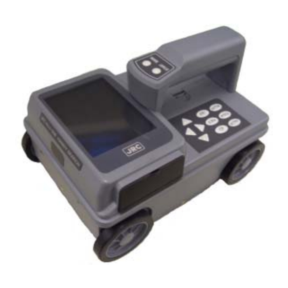
- Page 8 <Appearance of the NJJ-95B>...
-
Page 9: Table Of Contents
1.3 Configuration 1.4 Overall System Diagram 1.5 Configuration Parts Names and Functions 2.1 Handy Search NJJ-95B 2.2 Example of Scan Test Screen 2.2.1 Scan test screen example (during testing) 2.2.2 Scan test screen example (not during testing) 2.3 Parameter Settings Screen 2.3.1 Display color... - Page 10 3.2.5 Real time manual deduction processing 3.3 Operation while not Scan Testing 3.3.1 Mode switching 3.3.2 Sensitivity switching 3.3.3 Cursor operation 3.4 Image Processing 3.4.1 Manual surface wave processing 3.4.2 Peak Processing 3.4.3 Reproduction of original image 3.4.4 Fixed surface wave processing 3.4.5 Deduction processing 3.5 How to Determine Depths and Sample Scan Test Data 3.6 External Output Methods...
- Page 11 6.2 Daily Maintenance 6.3 Troubleshooting After-sales Service Disposal 8.1 Disposal of Used Battery Pack 8.2 Disposal of the NJJ-95B Specification 9.1 Handy Search NJJ-95B 9.2 Battery pack BP-3007 series 9.3 Charging Device BC-3008 series Where to Contact...
-
Page 12: Glossary Of Terms
Glossary of Terms Displays received waveform as it is. The conditions of concrete directly A mode underneath the Handy Search are displayed as reflected waveform in real time. Displays the vertical cross section of a scan point by gradating the B mode reflected waveform shown in A mode according to reflection intensity and continuously displaying it. -
Page 13: Description Of Equipment
Description of Equipment This equipment is indispensable for repairing/rebuilding and maintaining reinforced concrete structures using its accurate and speedy diagnostic technology. The Handy Search concrete internal probe vehicle, NJJ-95B, (hereafter called this radar) radiates electromagnetic waves through the surface of concrete and receives reflected signals from objects found inside such as reinforcing steel bars, cavities, or other objects that have different electrical characteristics from concrete. - Page 14 *1: For the case that the relative dielectric constant of concrete is a uniform 6.2 and the upper rebar has a diameter of 6 mm or more 2: The printer is optional. - 2 -...
-
Page 15: Features
1.2 Features This device has the following features: (1) The material of the object to be scanned can be either metallic or non-metallic Reflected electromagnetic waves are generated at an interface when the electrical property of an object is different from that of concrete. Thus, this radar can probe polyvinyl-chloride pipes and cavities (dependent on the position and size) as well as the reinforcing steel bars. - Page 16 However, the IrDA optical receptors for this unit and the printer must be set facing each other at a distance of 50 ~ 500 mm (without any obstacles between them). (7) Performing real time automatic surface wave processing Internal fixed surface wave data is used to automatically remove the wave reflected from the surface of the concrete during scanning enabling the showing of the reflected wave from rebar.
- Page 17 (13) Compact and light weight This radar weighs only about 1.1 kg, so it is easy to operate. (14) Operating with the battery pack and commercial power supply This radar can operate with the battery pack for about 1.5 hours (at normal temperature).
-
Page 18: Configuration
1.3 Configuration Standard components Table 1-1 shows the standard configuration of the Handy Search NJJ-95B Table 1-1 Standard Components Quan Remarks Name Model Number tity Handy Search NJJ-95B Battery pack BP-3007 series Battery charger BC-3008 series battery AC cable CB-A01-J1-E series... -
Page 19: Overall System Diagram
1.4 Overall System Diagram Table 1-1 shows the total configuration of the Handy Search NJJ-95B Memo Op key IrDA Trans Control section Compact Flash Trans Receive Distance Detector Rec. antenna Trans Figure 1-1 Overall System Diagram - 7 -... -
Page 20: Configuration
1.5 Configuration Figure 1-2 shows the external views of this radar. Plan view drawing Side view drawing Fig. 1-2. Handy Search NJJ-95B external dimensions diagram - 8 -... - Page 21 Rear view [Units in trigonometry: mm] - 9 -...
-
Page 22: Parts Names And Functions
Parts Names and Functions 2.1 Handy Search NJJ-95B This section shows the operation panel of this unit and explains the functions for each group. 10 11 Figure 2-1 Top View - 10 -... - Page 23 Table 2-1 Main Functions of Parts on the Handy Search Number in Label Function Square (None) Liquid crystal display (None) Battery holder GAIN Sets the sensitivity Sets each of the parameters. Decision key for start of image processing and various types of ENTER selection.
- Page 24 Figure 2-2 Side View Figure 2-3 Rear View - 12 -...
- Page 25 Table 2-2 Functions of Parts on the Side and Rear Panel Number in Label Function Square Mark indicating the scan test position. ▼ (None) Antenna face to radiate and receive electromagnetic waves POWER ON OFF Turns power on and off. (None) Equipment nameplate (None)
-
Page 26: Example Of Scan Test Screen
2.2 Example of the Scan Test Screen Describe the configuration for each of the scan test screens. 2.2.1 Scan test screen example (during testing) An example of a scan test screen (during scanning) is shown in Fig. 2-4. (1)Depth calibration value (7)Distance moved gauge (6)Antenna Mark (8)Battery capacity display... - Page 27 Depth gauge Displays a scanning depth gauge. The scanning depth gauge changes based on the depth calibration value. Fixed cursor The fixed cursor is the cursor that is used to designate surface waves used for real time manual deduction processing. See section 3.2.5 “Real Time Manual Deduction processing”...
-
Page 28: Scan Test Screen Example (Not During Testing)
2.2.2 Scan test screen example (not during testing) An example of a scan test screen (not during scanning) is shown in Fig. 2-5 (1)Depth calibration value (7)Cursor Coordinates (6)Antenna Mark (8) Distance moved gauge (9)Battery capacity display (2)Calibration method (10)Display range (3) Depth gauge (11)Cursor mark coordinates (4)Cursor... - Page 29 (4) Cursor Indicates a cursor mark on the scanning test screen and is a “criss-cross” cursor that is used to designate A mode waveform display points in B mode and for scrolling the sensing test screen. Sensitivity display Shows the scanning sensitivity setting. See section 3.3.2 “Switching Sensitivity”...
- Page 30 (13) Output data display Shows the output data destination set using the parameter settings screen. See section 2.3.10 “External Output” for how to set up external output. - 18 -...
-
Page 31: Parameter Settings Screen
2.3 Parameter Settings Screen While scanning is stopped, pressing of the 4 SET key enables switching the screen to the parameter settings screen (see Fig. 2-6) and each of the settings can be changed. To return to the scanning test screen, press the 4 SET key again. Settings Selections [Left column]... -
Page 32: Inversion Of The Screen
main unit. In order to change the display color, select “display color” from the settings using the ▲▼ cursor keys (inverting display) and switch to item selection using the cursor keys. Select “color” or “monochrome” using the ▲▼ cursor keys or use the cursor keys to switch to item selection. -
Page 33: Display Mode
Figure 2-7 Screen Inversion Function 2.3.3 Display mode This unit can scan/display data in both "B” mode (vertical cross section) and "BA” mode (vertical cross section and reflected waveform display). In order to change the display mode, select “display mode” from the settings using the ▲▼ cursor keys (inverting display) and switch to item selection using the cursor key. -
Page 34: Gradation System
2.3.4 Gradation system "Absolute value" or "Offset" can be selected for the gradation system. When "Color" is selected for "Display color," the absolute value gradation changes between Black → Indigo → Green → Yellow → Red as the A-mode amplitude increases as shown in Figure 2-8. The offset gradation changes between Black →... -
Page 35: Depth Calibration
2.3.6 Depth calibration The depth calibration is the scan depth obtained from the wave propagation speed and reflected time with the depth gauge corrected using the relative dielectric constant of concrete. The value must be changed based on the condition (such as moisture content) of the concrete being scanned. A large difference between the relative permittivity of the concrete being scanned and the depth calibration value will cause a large depth error. -
Page 36: Data No
2.3.8 Data No. Data is recorded and numbered when externally output. The data number (Data No.) is incremented each time data is recorded. In order to change the data No., select “Data No.” from the set up items using the ▲▼ cursor keys (invert display) and switch to item selection using the cursor keys. -
Page 37: Output Data Format
2.3.10 Output Data Format Set the external output destination of scan test data. The table below shows the relationship between external output destinations and output data formats. The currently set external output destination is indicated with the character displayed at the lower right of the scan test screen. -
Page 38: Return To Standard
2.3.13 Return to standard This function changes all the parameters other than "Data, time" back to the standard settings. In order to revert to standard settings, select “Return to Standard” from the set up items using the ▲▼ cursor keys (invert display) and switch to item selection using the cursor keys. -
Page 39: Cf Control Screen
2.4 CF Control screen While scanning is in off status and the 12 CF key is pressed, the screen switches to the CF control screen and compact flash memory control can be performed. Return to the scan test screen by pressing on the 12 CF key once more or “Cancel”. -
Page 40: Operating Method
Operating Method The numbers in squares in this chapter correspond to the numbers in Tables 2-1 and 2-2 on pages 8-11. Furthermore, keys are displayed on this unit using bold Gothic characters. WARNING Do not use any battery pack other than the BP-3007-A1 or any AC adapter other than the PW-3009-W.。... - Page 41 CAUTION Point the antenna surface in the direction of the probed object (concrete) while you are performing a probe.。 If it is pointed into the air or otherwise unsuitable direction, it can cause malfunction of other equipment or other such accidents. Do not use the NJJ-95B in the vicinity of a radio or TV set.
-
Page 42: Scanning Test Preparation
3.1 Scanning Preparation (1) Mounting the hand strap A hand strap for drop prevention is provided as standard with this radar. Mount the hand strap on the handle of the radar as shown in Figure 3-1, put your hand through the hand strap to grip the handle, and start sense testing. - Page 43 a) Mounting the battery pack (See Figure 3-2.) 1. Confirm that the 16 power switch is set to "OFF." 2. Open the battery cover 2 at the top of this unit, confirm the direction of the battery pack and put it into the battery holder. 3.
- Page 44 d) Dismounting the AC adapter 1. Confirm that the power switch 16 is set to "OFF," and disconnect the AC adapter cable from the socket outlet. 2. Pull out the AC adapter DC jack from this unit and close the connector cover for the 18 AC adapter input.
- Page 45 (1) Open the lid over the 8 (2) If the eject switch is extended, push in the switch. compact flash insert opening Compact Flash Memory Card (3) Insert the compact flash memory card Compact flash (4) Close the lid after insertion Figure 3-4 Mounting the Compact Flash Memory Card - 33 -...
- Page 46 (3) Press the eject again to enable pulling the (1) Open the lid of the compact flash out compact flash insert opening Compact flash (2) Push the eject so that the eject button is pushed in (4) Pull out the compact flash (5) Push the eject button so that the eject button is pushed in (6) Close the lid as was to start with...
- Page 47 Target Preparation for Scanning Using chalk (or similar) make markings on the concrete surface to indicate where to start testing (starting line) and where to scan (scan test line). Make sure the start line and the scan test line are orthogonal. (As necessary, in order to perform a retest, use and endpoint of the wall as a standard for the start line and scan test line) A scan test applicable set up example is shown in Fig.
-
Page 48: Scan Test
3.2 Scan Test 3.2.1 Power-on Procedure The 1 liquid crystal display lights up roughly 5 seconds after the power is turned on by turning on the 16 power switch, and next the initialization screen is displayed. After the initialization screen completes, the scan test screen is displayed. - Page 49 Figure 3-8 B Mode Sense Test Remarks • For the settings such as B/BA mode, Distance feed/Time feed, Absolute value gradation/Offset gradation, Depth calibration value, and Sensitivity, see section 2.3 “Parameter Setting Screen." • Automatic real-time surface wave processing may not eliminate all waves reflected by the concrete surface depending on the conditions.
-
Page 50: Sensitivity
3.2.3 Sensitivity When the power is turned on, sensitivity is set to “A shallow”. “A shallow” is a sensitivity setting that is applicable to the detection of rebar with a depth of less than 10 cm in general concrete. "A" of "A shallow" indicates the overall sensitivity; "shallow" indicates depth sensitivity. There are five levels for overall sensitivity: "-2, -1, A, +1, +2."... - Page 51 stopped. However, if the scan distance reaches 15m, the buzzer sounds twice and the scan test automatically finishes. - 39 -...
-
Page 52: Real Time Manual Deduction Processing
Real time manual deduction processing 3.2.5 Waves reflected by objects to be probed (e.g., reinforcing steel) at a position near the concrete surface are difficult to identify because they are combined with waves reflected by the concrete surface (called surface waves). This radar contains the standard surface wave data (fixed surface wave data) with which it eliminates the influence of the concrete surface waves in real time, thereby making it easy to identify the waves reflected by the objects to be probed. - Page 53 Remarks • Real time manual deduction processing performs the same processing as deduction processing for image processing during scanning. See section 3.4.5 “Deduction Processing" regarding deduction processing. • If image processing is performed for scan data by using real-time manual deduction processing and the surface wave data for manual surface wave processing is rewritten, data may not be reproduced during scanning.
-
Page 54: Operation While Not Scan Testing
3.3 Operation while not Scanning 3.3.1 Mode switching This radar can scan test/display data in both "B mode (vertical cross section)" and "BA mode (vertical cross section and reflected waveform display)". When the display mode is switched between "B" and "BA" after scanning, data scan tested in "B mode" is displayed in "BA mode," and data scan tested in "BA mode"... -
Page 55: Sensitivity Switching
Figure 3-10 B-mode/BA-mode Display 3.3.2 Sensitivity switching As sensitivity can be switched for the scan test results in the same way as during scanning, scanning does not have to be performed again after changing sensitivity. Sensitivity is displayed, for example, as "A shallow." "A" indicates the overall sensitivity; "shallow" indicates sensitivity to depths. - Page 56 Remarks • When switching from a scanning stopped state to scanning state, all of the cursor marks are erased. Cursor coordinates Cursor mark coordinates Cursor Mark Cursor Figure 3-11 Cursors and Cursor Marks - 44 -...
-
Page 57: Image Processing
3.4 Image Processing Image processing is processing that is performed on data input through scanning and enables easy deciphering of objects that are being probed for from the scanning results. This radar contains the following five types of image processing: Manual surface wave processing Peak processing Reproduction of original image... - Page 58 The operation is performed as described below. a) Press the 6 PRCS key . “Inverted display” is shown as the item for “Processing” at the bottom of the screen and operation switches to image processing. ▲▼ Set "Manual" using the cursor keys Use the cursor keys to move the cursor to a location where there is not a object to be probed in the sense test results.
-
Page 59: Peak Processing
3.4.2 Peak Processing Peak processing deletes multiple reflected waves of surface wave processing results and displays only the reflected waves from objects being probed (rebar etc.). Use this when it is difficult to see the depth of the objects being probed due to multiple reflected waves. Note that peak processing cannot be used for probing objects (e.g., cavities) that have a lower relative permittivity than concrete. - Page 60 Remarks • The display items at the bottom of the screen and their meanings are as follows: • Peak manual: Peak processing for the result of manual surface wave processing • Peak fixed: Peak processing for the result of fixed surface wave processing •...
-
Page 61: Reproduction Of Original Image
3.4.3 Reproduction of original image This processing restores the image processing result to the original state and displays unprocessed raw data. Procedure for reduction processing: (See Figure 3-14.) a) Press the 6 PRCS key. “Inverting display” mode will be indicated at the bottom right hand side of the screen as the operation switches to image processing from the manual mode.. -
Page 62: Fixed Surface Wave Processing
3.4.4 Fixed surface wave processing This image processing displays surface processing results using internal fixed surface waves. (Same as real time automatic surface wave processing results) Procedure for reduction processing: a) Press the 6 PRCS key. “Inverting display” mode will be indicated at the bottom right hand side of the screen as the operation switches to image processing from the manual mode. - Page 63 Remarks • When "Deduction" is set with the cursor keys ▲▼ after manual surface wave processing (including real-time manual deduction processing) and deduction processing, the image generated through deduction processing using the reflected wave of cursor position (indicated by “↓”) of the last executed processing is displayed. (Deduction processing can be newly performed by moving the cursor and pressing 5 ENTER.)) →...
-
Page 64: How To Determine Depths And Sample Scan Test Data
3.5 How to Determine Depths and Sample Scan Test Data The reflected waves shown in the scan test example in Figure 3-16 are reflections of rebar. (↓ position) The position of the object to be probed (e.g., reinforcing steel) in the traveling direction is determined as the peak of the reflected wave. - Page 65 Position of rebar shown among reflected waves of the scan test results (The mark is not actually shown in the sense test results.) tart position 位置 ス タ ート Start Measurement directio スタ ート位置 測定方向 Measurement direction 測定方向 Vertical cross sectional drawing of 300mm 300mm Vertical cross sectional draw ing...
-
Page 66: External Output Methods
3.6 External Output Methods This unit is equipped with functions for printing the screen to a special printer (option) and a function for saving scan test data to a compact flash memory card. The following explains how to use the functions: 3.6.1 Printer Output (1) Setting of an output destination Press the 4 SET key on the scan test screen, and set "Printer (I)"... - Page 67 Remarks Remarks • For details on the printer, see the printer instruction manual. • For details on the printer, see the printer instruction manual. • To stop in the middle of printing, press any key. • To stop in the middle of printing, press any key. •...
-
Page 68: Data Saving In Compact Flash Memory
3.6.2 Data saving in compact flash memory Notes Mount/remove the compact flash memory card while the power switch of this unit ● is off. Make sure of the insertion direction before mounting the compact flash memory card. ● ● Operation of this unit has been confirmed with compact flash CF115-512M manufactured by IO Data. - Page 69 Header section The following shows a sample configuration of the header section and explains the items. The control codes in the header section are as follows: [0x0D] = CR, [0x0A] = LF, and [0x1A] = EOF. Sample configuration of the header section: (1)NJJ-95 B Measurement Data ###[0x0D][0x0A] (2)Date : 31.12.06[0x0D][0x0A] (3)Time : 23:59[0x0D][0x0A]...
- Page 70 (14)Y coordinate of the n-th cursor marker (15) Header section ending data (16)EOF Data section Scan test data is configured as a collection of 1-line data. One-line data is fixed to a length of 769 bytes as follows: 1 byte of header + 768 bytes of scan test data = 769 bytes The header represents line attributes in the following format: A0-Bit7(MSB) A0-Bit6...
- Page 71 Details on 768 bytes of scan test data: Scan test data per line includes 512 points, and 1-point data consists of 12 unsigned bits. Two-point data is sent after being re-listed as 3 bytes, so a total of 512 points (= 768 bytes) are sent.
- Page 72 (3) Saving data to compact flash memory Procedure for saving data in compact flash memory: Setting of an output destination Press the 4 SET key on the scan test screen, and set "CF (text)" or "CF (binary)" for "External output" on the parameter setting screen. Setting of a data number An arbitrary number can be assigned to scanned data by setting the number for "Data No."...
- Page 73 Display of thumbnails Figure 3-17 CF Control Screen - 61 -...
-
Page 74: Cf Control Screen
3.7 CF Control Screen When not scan testing, if the 12 CF button is pushed, operation will be switched to the CF control screen. Once at the CF control screen, thumbnail image display can be viewed. Also, data storage, data erasure, and initialization for the compact flash memory card can be executed. To return to the measurement screen, select "Cancel"... -
Page 75: Deleting Saved Data
If there is not any data or data opened from CF on the scan test screen An example where there is data that has not been saved or data opened from CF on the scan test screen Select "Read" and press the The screen scrolls ENTER key. - Page 76 To delete the data, select "Yes" and Select "Delete" and press the ENTER key. press the ENTER key. Figure 3-19 Deleting Saved Data - 64 -...
-
Page 77: Method For Initialization Of Compact Flash
3.7.4 Method for initialization of Compact Flash Select "Initialization" on the CF control screen using the cursor keys , and press the ENTER key. The message "Do you want to initialize memory? Yes/No" is displayed. Select "Yes" using the cursor keys , and press the ENTER key. - Page 78 Press the ENTER key to start initialization Select "Yes" Message indicating compact flash After initialization, all data is erased memory is being initialized Figure 3-20 Initializing Compact Flash Memory - 66 -...
-
Page 79: Power-Off Procedure
3.8 Power-off Procedure When scan testing is finished, set the 16 power switch to "OFF." Notes • All scan test data that is not saved in the compact flash memory is deleted when the power is turned off. 3.9 Clearing up the radar and accessories Turn off the power, disconnect all cables the radar, and put them together with the radar into the provided storage box. -
Page 80: About The Battery Pack And Charger
3.10 About the Battery Pack and Charger WARNING Do not short-circuit the terminals of the battery charger or battery pack. Doing so could cause fire, explosion, or breakdown. Do not disassemble, modify, heat, or throw the battery pack on fire. Doing so could cause fire, explosion, or breakdown. -
Page 81: Battery Pack Bp-3007 Series
3.10.1 Battery pack BP-3007 series The battery pack BP-3007 series, which is commonly used with the Handy Search and printer (optional), contains a rechargeable lithium ion battery. While the battery pack is fully charged, it can operate the Handy Search for about 1.5 hours. (1) Mounting/dismounting the battery pack See "Section 3.1 Preparations for Sense Testing", for how to mount/remove the battery pack. - Page 82 Remarks • The battery pack is charged just enough for the radar's test operation before it is shipped. The battery pack needs to be charged when used for long operation. • The battery pack should be charged immediately before being used. •...
- Page 83 B Terminals A Charge confirmation mark Figure 3-22 Battery Pack - 71 -...
-
Page 84: Charging Device Bc-3008 Series
3.10.2 Charging Device BC-3008 series The battery charger BC-3008-series is exclusively used with the battery pack BP-3007-series. When the battery pack is in the availability "0" state, charging will take about 2.5 hours. (1) Procedure for using the charger Mount the battery in the charger (see Fig. 3-23-(1)) While pushing the battery pack against the charger, slide it in the direction indicated by the arrow. - Page 85 Shutter Charge lamp Figure 3-23 Battery Charger - 73 -...
-
Page 86: Options
Options WARNING Do not use any battery pack other than the BP-3007-A1 or any AC adapter other than the PW-3009-W.。 Doing so could cause fire, electric shock, or breakdown. Do not short-circuit the terminals of the battery charger or battery pack. Doing so could cause fire, explosion, or breakdown. -
Page 87: Printer Dpu-3445 Series
4.1 Printer DPU-3445 series Printer DPU-3445-series is of the thermal type and prints out the records of data scan tested with the Handy Search. Notes • Thoroughly read the "printer instruction manual" to use the printer correctly and safely. Remarks •... -
Page 88: Printer Specification
Table 4-1 Printer's Main Parts and Functions Name Function Turns "ON or "OFF" the power. To turn on the power, hold the button down until the power lamp Power button 1 turns on. To turn the power off, hold the button down until the power lamp turns off. -
Page 89: Connecting The Battery Pack/Power Source
4.1.3 Connecting the battery pack/power source Notes • Confirm that the power switch is set to "OFF" before mounting/dismounting the battery pack or the AC adapter. Mounting the battery pack (See Figure 4-2 A.) Align the printer's battery connecting terminals with the battery pack's connecting terminals, and push the battery pack in the direction indicated by the arrow. - Page 90 (4) Mounting the Paper Holder and Loading Paper CAUTION When loading/unloading printing paper, be careful not to cut or jam your fingers in the printer. Mount the paper holder on the printer and then load paper. 1.Insert the paper holder hooks into the square holes (upper) in both sides of the platen cover of the printer.
- Page 91 6.Close the paper cover, and slide it in the opposite direction of step 3 until a click sound is heard. The paper cover will be locked. Note that paper will drop if the paper cover is not locked securely in this step. Fig.
- Page 92 (7) Printing of Handy Search scan test data Before starting to print, check the external output destination setting on the parameter setting screen. Make sure that external output is set to printer (I). After the confirmation, return to the scan test screen, and perform the following printing procedure: Press the 13 OUTPUT key.
-
Page 93: Ac Adapter Pw-0904-W1 Series
4.2 AC Adapter PW-0904-W1 series The AC adapter PW-3009 series is used with both the Handy Search and printer. 4.2.1 AC Adapter Specification The specification for the AC adapter is shown below. Input voltage: :AC 100 to 240V Output voltage :DC 9.3V Output current :4A... -
Page 94: Theory
Theory 5.1 Principle of Operation The principle of this radar is basically the same as for general radars widely used at present. Electromagnetic waves are transmitted from the antenna toward the concrete as shown in Figure 5-1. The electromagnetic waves are reflected by an interface with the reflecting objects (e.g., reinforcing steel bars or cavities) whose electrical property is different from that of concrete. -
Page 95: Applicable Conditions
Velocity V of electromagnetic waves in concrete is obtained from the following formula: C V= (m/s) ε r C: Velocity of electromagnetic waves in vacuum (in air) (3 × 10 m/s) : Relative dielectric constant of concrete (6 to 11 in the example) Distance D to the reflecting object is obtained from the following formula: 1... - Page 96 D<75mm → L>75mm Concrete Difficult to implement D D≤75mm → L≥D Rebar L - 84 -...
-
Page 97: Maintenance Inspection
Maintenance Inspection WARNING Do not attempt to disassemble, modify, or repair the NJJ-95B. Doing so could cause fire, electric shock, or breakdown. When the power cord is damaged (exposed core wire, open circuit failure, or broken sheath), please contact our headquarters on Page 93 or our nearest branch office, sales outlet, or service station for a replacement power cord. -
Page 98: Troubleshooting
6.3 Troubleshooting The radar's states listed below are not always a sign of trouble. Check for the radar again before asking for repair. Main unit state Check Items and Response • Check if the battery pack is mounted. Mount a fully charged battery pack according to section 3.1 “Preparations for Scanning."... - Page 99 Main unit state Check Items and Response message "Turn • Check if the printer settings have been initialized. OFF/ON the printer" is →Turn OFF/ON the printer, and press the OUTPUT key again to displayed when start printing. OUTPUT key is pressed. The message "Charge •...
-
Page 100: After-Sales Service
fter-sales Service If this radar malfunctions, read section 6.3 “Troubleshooting" carefully, and check the radar again. If the radar still malfunctions, stop using it, and contact our nearest branch office, sales outlet, or service station. ●Information to be reported Product name, model number, and serial number Detailed information about the abnormal state Company/organization name, address, and telephone number For inquiries about after-sales service, contact our nearest branch office, sales outlet, or service station. -
Page 101: Disposal
Disposal WARNING Before disposing of the used lithium ion battery, insulate the charging terminals by taping or the like. Otherwise, the battery could cause fire or explosion if short-circuited. 8.1 Disposal of Used Battery Pack Discharge the used battery pack (lithium ion battery) completely, insulate the charging terminals by taping or the like, and then dispose of it as nonflammable refuse. -
Page 102: Specification
Specification 9.1 Handy Search NJJ-95B Item Specifications System Radar system Transmission output About 10 V (pulse output) Primary objects Concrete wall, and reinforcing steel bars under the floor probed Covering depth 5 ~ 300 mm (case where relative permittivity of concrete is 6.2 and the diameter of the... - Page 103 About 149 (W) x 147 (H) x 216 (D) mm Dimensions Approximately 1.1kg Weight - 91 -...
-
Page 104: Battery Pack Bp-3007 Series
9.2 Battery pack BP-3007 series Item Specifications Battery Lithium ion battery Nominal capacity 1500 mAh Nominal voltage 7.2 V Temperature range 0∼+40 °C (when charging) Temperature range −10∼+60 °C (when discharging) Dimensions About 38 x 70 x 20mm Weight Approximately 103g 9.3 Charging Device BC-3008 series Item Specifications... -
Page 105: Where To Contact
For inquiries about this radar, contact our main office below for the nearest branch office, sales outlet, or service station. Japan Radio Co. Ltd. Section-I, International Business Department. Sales and Marketing 1-1 Shimorenjaku 5 Chome, Mitaka-shi, Tokyo 181-8510, Japan TEL:+81 422 45 9867 FAX:+81 422 45 9969 Web site: http://www.jrc.co.jp - 93 -...
Need help?
Do you have a question about the Handy Search NJJ-95B and is the answer not in the manual?
Questions and answers