Table of Contents
Advertisement
Advertisement
Table of Contents

Related Manuals for JRC Radar 3000


Summary of Contents for JRC Radar 3000
- Page 2 ● Store the manual in a safe location so that it does not become lost or damaged. ● Observe standard storage and handling procedures for electronic equipment. ● If after proper installation RADAR 3000 appears to be defective, please con- tact your JRC sales or service representative for assistance.
-
Page 3: Operating Precautions
Never sit on the scanner unit. The radome and/or the parts in the scanner unit may be damaged. CAUTION Use your RADAR 3000 system properly by following the instructions in this manual. Incorrect operation can detract from optimum system performance. -
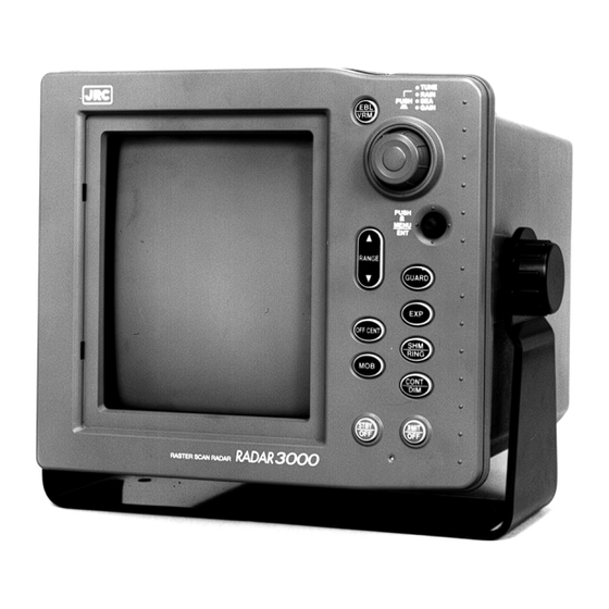
Page 4: Equipment Photograph
Equipment Photograph SCANNER UNIT NKE-1046 DISPLAY UNIT NCD-3744... -
Page 5: Table Of Contents
Table of Contents Symbol Used In This Manual ------------------------------------------------- I Operating Precautions --------------------------------------------------------- II Equipment Photograph ------------------------------------------------------- III Radar Glossary of Terms ----------------------------------------------------- VI SECTION 1 INTRODUCTION FUNCTION -------------------------------------------------------------- 1 FEATURES --------------------------------------------------------------- 1 COMPONENTS --------------------------------------------------------- 2 CONSTRUCTION------------------------------------------------------- 3 SECTION 2 OPERATING CONTROLS AND FUNCTIONS CONTROL PANEL ----------------------------------------------------- 5 SECTION 3... - Page 6 EQUIPMENT DISPOSAL ------------------------------------------- 42 DISPOSAL OF USED BATTERY ---------------------------------- 42 DISPOSAL OF USED MAGNETRON ---------------------------- 42 SECTION 8 SPECIFICATIONS GENERAL -------------------------------------------------------------- 43 SCANNER UNIT ------------------------------------------------------ 44 DISPLAY UNIT ------------------------------------------------------- 44 APPENDIX Fig. 1 RADAR 3000 SCANNER UNIT (NKE-1046) RADOME TEMPLATE...
-
Page 7: Radar Glossary Of Terms
Radar Glossary of Terms The following is a list of abbreviations and acronyms which may be used in the text of the manual. Analog to Digital conversion Alarm In, also known as the approach alarm. For targets set zone. approaching a preset zone. Central Processing Unit Electronic Bearing Line Expansion... -
Page 8: Introduction
INTRODUCTION 1.1 FUNCTION The JRC RADAR 3000 Radar is compact raster scan radar with a 4 kW trans- mitter and a 7-inch cathode ray tube. Except for special tubes, they are all made up of solid state device for improved reliability. -
Page 9: Components
1.3 COMPONENTS Table 1-1 indicates a listing of items that are included with your new radar system. Description Model No. or Code No. Remarks Radar 3000 system JMA-1541 Scanner Unit NKE-1046 Display Unit NCD-3744 Sun Shield MTV301854A 12-cores composite cables... -
Page 10: Construction
1.4 CONSTRUCTION FIG. 1-1 DISPLAY MOUNTING DIMENSIONS FIG. 1-2 SCANNER MOUNTING DIMENSION INTRODUCTION... -
Page 11: Operating Controls And Functions
SECTION 2 OPERATING CONTROLS AND FUNCTIONS DISPLAY UNIT VRM/EBL Key J-DIAL JOYSTICK Range Up/Down Key GUARD Key EXP Key OFFCENT Key SHM/RINGS Key Brilliance/Dimmer Key MOB Key Transmit/off Key Stand-by/off Key FIG. 2-1 OPERATING CONTROLS OPERATING CONTROLS AND FUNCTIONS... -
Page 12: Control Panel
2.1 CONTROL PANEL ① Stand-by/off Key ・ Turn ON power to Display and Scanner and activates 90 second countdown timer. ・ Press STBY/OFF key to Stand-by mode while in the Transmitting mode. ・ Press STBY/OFF and X-MIT/OFF keys simultaneously to shut off. ②... - Page 13 ⑦ EXP Key ・ Target Expander ON/OFF. ⑧ OFFSET Key ・ Places origin at any point on screen up to 2/3 radius. Inop on 24 nm range. ⑨ SHM/RINGS Key ・ Enables or disables the fixed range rings alternately. ・ Momentarily disables the Heading Flash while key is held depressed. ⑩...
-
Page 14: Installation
3.2 PLANNING THE INSTALLATION The layout for installing the RADAR 3000 should be planned to give the best operation and service aboard your particular vessel. In general, the scanner unit should be mounted as high as possible above the waterline. - Page 15 FIG. 3-1 GENERAL SYSTEM DIAGRAM INSTALLATION...
-
Page 16: Mounting The Display Unit
3.3 MOUNTING THE DISPLAY UNIT When planning the installation for your display unit, the following conditions should be considered to ensure dependable and trouble free operation. 1) The mounting location should be easily accessible to allow operation of the front panel controls. 2) There should be adequate ventilation. - Page 17 FIG. 3-2 DISPLAY MOUNTING DIMENSIONS FIG. 3-3 SCANNER MOUNTING DIMENSION INSTALLATION...
-
Page 18: Mounting The Scanner Unit
3.4 MOUNTING THE SCANNER UNIT Selecting an adequate location for the scanner unit requires careful consider- ation. On many small vessels, the unit can be installed on a mast platform, on an arch, or on a bridge structure near the ship’s centerline. The radiator beam should not be obstructed by nearby large objects. -
Page 19: Electrical Connection
3.6.1 DC POWER CABLE The RADAR 3000 will work with any ship’s mains within the 10.2 to 42 V range, since it contains a power regulator circuit. Connect the power cable to a DC source. The power cable normally should be wired through the circuit breaker. - Page 20 1. NAV-AID (NMEA0183 “RMC,RMA,VTG”) 2. Compass (NMEA0183 “VHW”) WAYPOINT: 1. NAV-AID (NMEA0183 “RMB,BWC”) Using the outline of FIG 3-5 as a guide, connect the RADAR 3000 to your NAV-AID and compass. ① NAV (Data Output) NAV-AID ② NAV (Data Ground) NAV-AID ③...
- Page 21 FIG. 3-6 INTERCONNECTION DIAGRAM INSTALLATION...
-
Page 22: Initial Operation And Check Out
3.7 INITIAL OPERATION AND CHECK OUT 3.7.1 INSPECTION AFTER THE INSTALLATION After completing the installation and prior to energizing the equipment, it is necessary to assure that all the steps of the installation were accomplished in accordance with the instructions. (1) The cables are not crimped or damaged. - Page 23 ⑥ Put the EBL over the desired target using the J-DIAL, and press the JOY- STICK. ⑦ Move the EBL so that the target will be displayed on the SHM. ⑧ Press the JOYSTICK to end the bearing adjustment mode. 3.7.4 DISPLAY TIMING (ZERO NM ADJUSTMENT) This alignment must be made when the radar unit is installed.
-
Page 24: Stc Preset
① Set the range scale to 3 NM. ② Set the gain control to desired level. ③ Set the SEA, RAIN and IR to Off. ④ Press and hold the JOYSTICK for the initial setting menu. ⑤ Select TUNE PRESET by using the JOYSTICK, and press the JOYSTICK. ⑥... - Page 25 3.7.7 BUZZER VOLUME At the time of shipment, the Buzzer sound has been set to maximum position. When it is necessary to lower the volume. ① In the initial setting menu select BUZZER. ② Adjust the suitable buzzer sound level using the J-DIAL. ③...
-
Page 26: Operation
SECTION 4 OPERATION Generally the operation of the RADAR 3000 is easy straight forward. However the navigator who knows the layout and understands the functions of various controls will obtain the best performance from his equipment. 4.1 LAYOUT OF CONTROLS Layout of the control are shown in FIG 4-1. -
Page 27: Turning The Radar On And Off
4.2 TURNING THE RADAR ON AND OFF TO TURN ON Press the STBY/OFF key. TO TRANSMIT Press the X-MIT/OFF key. TO STAND-BY Press the STBY/OFF key. TO TURN OFF Press the STBY/OFF and X-MIT/OFF key simultaneously. After pressing the STBY/OFF key, the countdown timer is displayed on the screen. - Page 28 INTERFERENCE REJECTION "ON" TARGET EXPANDER "ON" EBL Unit RING INTERVAL (nm) OWN SHIP SPEED DATA* SELECTING JOG DIAL RANGE SCALE (nm) VRM Number Range Unit PPI Display Mode SEA RAIN GAIN LEVEL INDICATOR TUNE INDICATOR Motion Mode Bearing reference OWN SHIP COURSE DATA* EBL Number Joystick Mode Cursor data/Waypoint data*...
-
Page 29: Selecting A Range
4.5 ADJUSTING TUNING The RADAR 3000 is setting Auto Tune mode at the power ON. If wish to manual tuning, required to select Manual Tune mode by using menu (Refer to 4.27). -
Page 30: Reducing Sea Clutter
4.6 REDUCING SEA CLUTTER CAUTION On short range scales, the setting of the sea clutter control should never be advanced so high as to completely obliterate all clutter, since this setting could prevent the detection of close-in target echoes. The sea clutter control is normally used on the shorter ranges to suppress the effect of sea clutter close to own’s ship. -
Page 31: Setting Offsent
4.10 SETTING OFFCENT By pressing the OFFCENT key, the display is into off-center mode by 2/3 ra- dius, expanding the display area in the direction instructed by JOYSTICK. Press the key a second time to return the display to normal. Off-center mode off Off-center mode on 4.11 RANGE MEASUREMENT... -
Page 32: Bearing Measurement
④ Rotate the J-DIAL clockwise for outer direction or counterclockwise for inner direction to move the #2 variable range marker. The actual target distance appears on the center top of the screen in selecting unit. To turn off the #2 VRM, selects the FUNCTION-#2 VRM-OFF on the menu sheet. -
Page 33: Setting Guard
③ Selects #2 EBL-SET, then press the JOYSTICK. The EBL2 appears high- light on the upper right corner of the display. ④ Rotate the J-DIAL clockwise or counterclockwise to move the #2 EBL on the center of the target. The actual target bearing appears on the cen- ter top of the screen in selecting unit. -
Page 34: Rings
To activate the memorized alarm zone, just press and hold the GUARD key until the display beeps. Your memorized zone will reappear. The zone will be displayed as an IN mode alarm. If you want to change to an OUT mode alarm, press the GUARD key. -
Page 35: Read Out Dimension Of Bearing
4.18 READ OUT DIMENSION OF BEARING This selects the bearing for heading flush, EBL, cursor and waypoint to work in either magnetic or true bearings. When magnetic bearing is selected, displayed character “M” appears. When true bearing is selected, displayed character “T” appears. -
Page 36: Timed-Tx Mode
・ The screen is disturbed. ・ The machine accepts no key input. While manipulating, initialize RADAR 3000 by following the steps given be- low. (a) Press the STBY/OFF and X-MIT OFF keys simultaneously. The RADAR 3000 is turned off. -
Page 37: Operating Menu
4.27 OPERATING MENU Press the JOYSTICK (MENU/ENT), and the first menu sheet will be appear. The JOYSTICK is used to select a particular menu. The particular menu will be highlighted character. Pressing the JOYSTICK (MENU/ENT) again will return the display to the nor- mal video presentation. - Page 38 Spanish Menus MENU OPERATION...
- Page 39 Norwegian Menus MENU OPERATION...
- Page 40 Menu Item Description FUNCTION Selects #2VRM. Selects #2EBL. Doubles the size of the image at a given position on the PPI screen. Selects true or relative motion dis- play. Selects the heading mode. Defines the receiver tuning mode. Display the past tracks (wakes) of the echo as an after-glow on the PPI screen.
- Page 41 DISPLAY Displays the position of the own ship or waypoint in terms of latitude and longitude (L/L) or time difference (TD). Display the waypoint on the PPI screen. Selects the unit of VRM or cursor range from NM (nautical miles), KY (kiloyards), and KM (kilometers).
- Page 42 RADAR SET-UP Sets the guard zone alarm, sensitivi- ty in terms of intensity of the echo image. Sets the width of the transmitter pulses. The narrower the pulse width, the better the range resolution is. The wider the pulse width, the bet- ter the sensitivity is.
- Page 43 INITIAL SETTING MENU (LONG PRESS) Adjusts the bearing on the PPI screen. Adjusts the range of the echo image on the PPI screen and the rage of the actual target. Makes coarse tuning of the receiver. Adjusts the intensity of the sea clutter.
-
Page 44: Display Of Radar Transponder
4.28 DISPLAY OF RADAR TRANSPONDER SART (Search and Rescur Radar Transponder) is life preserving device ap- proved by GMDSS which is used for locating survivors in the event of a disas- ter or distress. SART operates in the 9 GHz frequency band. When it receives a radar signal (interrogating radio wave) of 9 GHz transmitted by a rescue ship or aircraft radar, SART transmits a series of respouse signals to the searchers to indicate the distress position. -
Page 45: Maintenance
MAINTENANCE The purpose of this section is to provide servicing instructions for the service technician. The RADAR 3000 is designed to provide long periods of trouble free operation. However, environmental and other factors may required this equipment to be serviced. -
Page 46: Cleaning The Scanner Unit
(2) Check for evidence of any corrosion of the scanner unit, display unit, or its cable and connectors. Clean as required. (3) Check that the cable connector is secure. 5.2 CLEANING THE SCANNER UNIT Wash the exterior of the scanner unit with fresh water. But do not immerse the unit. -
Page 47: After-Sales Service
It is very impor- tant that you take time to fill out this card. The warranty registration card should be returned to the nearest JRC service center immediately after your purchase in order to receive full warranty benefits. -
Page 48: Radar Failure Checklist
RADAR FAILURE CHECKLIST When ordering for repair, check the following items, fill in the sheet and send it to us. If there is any uncertain items, contact your ship and give us correct information on the product. Ship name: Phone: Fax: Radar general model name: JMA-1541 Serial No.:... -
Page 49: Disposal
SECTION 7 DISPOSAL 7.1 EQUIPMENT DISPOSAL Dispose of this equipment by following the ordinances or regulations of the local authorities in charge of the disposal site. 7.2 DISPOSAL OF USED BATTERY WARNING Before disposing of used lithium battery, insulate by affixing tape to the positive and negative terminals or by other means. -
Page 50: Specifications
SECTION 8 SPECIFICATIONS 8.1 GENERAL Maximum range: 24 NM Minimum range: Less than 25 m on the 0.125 NM range Range scales: Range Number of Range ring (NM) Rings Interval(NM) 0.125 0.0625 0.25 0.125 0.25 0.75 0.25 0.25 12.0 24.0 Range discriminations: Less than 25 m Better than ±... -
Page 51: Scanner Unit
8.2 SCANNER UNIT Dimensions: Diameter 620 mm Height 275 mm Mass: Approx. 9.5 kg Polarization: Horizontal Beam width: Horizontal 4°nominal Vertical 25° Sidelobes: Less than − 21 dB Rotation: Approx. 27 rpm Transmitter frequency: 9410 30 MHz ± Peak power output: 4 kW 0.08 µs/2250 Hz Pulse length/PRF:... - Page 52 Alarm: Audible alarm with zone mark 10. Off Center: 2/3 radius 11. Planned TX: Rotation period 10, 20 or 30 scans Repetition period 3, 5, 10, 15 min. 12. Language: English, Spanish, Norwegian 13. Features: VRM(2), EBL(2), Cursor with LL, Interference rejection, Target expansion, Target alarm, LL or TD readout, Waypoint with LL, Offset, Timed TX, Target Trail,...
-
Page 53: Radar 3000 Scanner Unit (Nke-1046) Radome Template
4-φ0.47" (φ12mm) 5 9/16" (141.7mm) 3.149" (80mm) φ1.14" (φ29mm) BREATHING TUBE CABLE 5 9/16" forword ACCESS (141.7mm) φ0.591" (φ15mm) 4.330" (110mm) Fig.1 RADAR 3000 SCANNER UNIT (NKE-1046) RADOME TEMPLATE... - Page 54 Akasaka Twin Tower(Main) 1-1,Shimorenjaku 5-chome,Mitaka 17-22,Akasaka 2-chome, Tokyo 181-8510 JAPAN Minato-ku,Tokyo 107-8432 JAPAN Phone:+81-422-45-9111 Maritime Sales Department Fax :+81-422-45-9110 Phone:+81-3-3584-8833 Fax :+81-3-3584-8757 International Business Department Phone:+81-3-3584-8836 Fax :+81-3-3584-8878 Communications Equipment Marketing Department Phone:+81-3-3584-8845 Fax :+81-3-3584-8879 ●JRC (UK) Limited Overseas Subsidiaries 136, 1st Floor, Friars House, 157/168 Blackfriars Road, London SE18 EZ, U.K. Phone:+44-20-7261-1188 Fax :+44-20-7803-0996 ●U.S.A. ●Netherlands Overseas Branch Offices Japan Radio Co.,Ltd./Seattle Branch Japan Radio Co.,Ltd. Amsterdam Branch 1011 SW Klickitat Way Cessnalaan 40-42,1119NL Schiphol-Rijk Bldg.B, Suite 100 The NETHERLANDS Seattle, WA 98134 U. S. A. Phone:+31-20-658-0750 Phone:+1-206-654-5644...
Need help?
Do you have a question about the Radar 3000 and is the answer not in the manual?
Questions and answers