Table of Contents
Advertisement
Quick Links
Advertisement
Table of Contents

Related Manuals for NetComm NTC-100


Summary of Contents for NetComm NTC-100
- Page 1 User Guide 4G LTE Cat M1/NB1 Industrial IoT Serial Modem Doc No. UG01037...
- Page 2 NetComm Wireless accepts no responsibility for any loss or damage resulting from errors or delays in transmission or reception, or the failure of the NTC-100 to transmit or receive such data.
- Page 3 Document history This guide covers the following products: NetComm - 4G LTE Cat M1/NB1 Industrial IoT Serial Modem V E R . D O C U M E N T D E S C R I P T I O N D A T E v1.0...
-
Page 4: Table Of Contents
Mounting the device ................................ 18 Connecting the data/power cables ................................... 19 Powering the NTC-100 serial modem via 5V Micro USB socket ..........................19 Powering the NTC-100 serial modem via Y-cable ..............................20 Accessing the NTC-100 via terminal emulator ........................21 Command Line Interface Guide............................ - Page 5 AT+SERIAL_FORMAT ......................................... 41 AT+SERIAL_MODE ........................................41 AT+SERIAL_ON_START ......................................42 AT+SERIAL_PARITY ........................................42 AT+SERVER ..........................................43 AT+SMS ............................................43 AT+SMS_ACK..........................................44 AT+SMS_DIAGNOSTICS ......................................44 AT+SMS_PASSWORD ......................................... 45 NTC-100 – User Guide 5 of 103 UG01037 v1.1 25 September 2018 © NetComm 2018...
- Page 6 ........................................... 75 get daily_sms_limit ........................................ 75 get fail_count ......................................... 75 get force_reconnect ......................................75 get force_reset ........................................75 get ftp_para ........................................... 75 get hw_version........................................75 NTC-100 – User Guide 6 of 103 UG01037 v1.1 25 September 2018 © NetComm 2018...
- Page 7 ................................81 set sms=XXXXXXXXXX,”message content” ..............................81 set smspassword=XXXXXX ....................................81 set web_file ..........................................81 set web_host .......................................... 81 set web_pass.......................................... 82 set web_path ......................................... 82 NTC-100 – User Guide 7 of 103 UG01037 v1.1 25 September 2018 © NetComm 2018...
- Page 8 Electrical Specifications ....................................... 95 Environmental Specifications / Tolerances ................................96 Product Service and Support ............................97 Troubleshooting ................................97 FAQs ....................................98 Appendix A: Tables ................................. 99 NTC-100 – User Guide 8 of 103 UG01037 v1.1 25 September 2018 © NetComm 2018...
-
Page 9: Introduction
A computer with a terminal emulation program (such as PuTTY), a serial port, an appropriate power supply and a device to connect to the NTC-100 modem after configuration has been completed. A SIM card in 2FF format is required for cellular connection. -
Page 10: Safety And Product Care
Disconnect the power line from the device before servicing. Transport and handling When transporting the NTC-100, we recommend using the original packaging. This ensures the product will not be damaged. Important – In the event that the product needs to be returned, ensure it is securely packaged with appropriate padding to prevent damage during courier transport. -
Page 11: Product Introduction
Deploy IoT applications in any environment with access to a wide input voltage range, extreme temperature tolerance (-30˚C to 70˚C) and a lockable SIM tray. For easy installation, the compact NTC-100 also includes a DIN rail and flexible wall mount options including a removable mounting bracket. -
Page 12: Package Contents
1 x DIN rail mounting bracket 1 x Torx screw 1 x Quick start guide If any of these items are missing or damaged, please contact NetComm Support immediately by visiting the NetComm Support website at: http://support.netcommwireless.com/ . Accessories Additional cables are available for purchase separately. Contact your NetComm Wireless sales representative to order additional cables. -
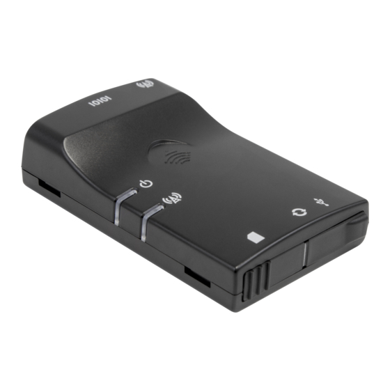
Page 13: Physical Dimensions And Indicators
Physical dimensions and indicators LED indicators The NTC-100 serial modem uses two LEDs to display the current system and connection status. L E D S T A T U S D E S C R I P T I O N I N D I C A T O R The power is off. -
Page 14: Physical Dimensions
Below are the physical dimensions of the NTC-100 as well as the physical dimensions of the mounting bracket which can be used to attach the NTC-100 to a Type-O DIN Rail or to provide a wall / ceiling mount. Figure 1 – NTC-100 Dimensions... -
Page 15: Interfaces
SMA Female connector for use with a suitable Cellular antenna socket LTE antenna. Table 4 - Interfaces Note – The driver required for the Micro USB virtual COM port is available from the NTC-100 Product Support page at: http://support.netcommwireless.com/product/m2m/NTC-100. NTC-100 – User Guide 15 of 103 UG01037 v1.1 25 September 2018... -
Page 16: Hardware Installation
Hardware installation Connecting the antenna Connect the antenna to the SMA connector on the NTC-100 serial modem by placing it on the SMA connector and turning it in a clockwise direction. Inserting the SIM card Ensure that the NTC-100 is not connected to the power cable before proceeding. - Page 17 To remove the SIM card, push it in again and it will unlock. Figure 4 - Inserting a SIM card into the NTC-100 SIM card slot Slide the cover back to the left and then push the right side closed.
-
Page 18: Mounting The Device
Mounting the device The NTC-100 can be mounted on the wall or a DIN rail by using the mounting bracket. The mounting bracket is made from polyamide, which is a flexible material. DIN rail mounting The NTC-100 serial modem mounting bracket has been designed to fit a TS 35 Type-O DIN rail with a 25mm core. -
Page 19: Connecting The Data/Power Cables
USB port driver is installed. Connect a standard USB Type A to USB Micro Type B cable (not included) between the NTC-100 serial modem and a powered USB port on your device (e.g. computer). The USB cable provides the NTC-100 serial modem with power and an emulated serial port input. -
Page 20: Powering The Ntc-100 Serial Modem Via Y-Cable
Figure 9 – Powering the NTC-100 serial modem via Y-cable After powering up, the NTC-100 serial modem is ready to establish a serial communication link. See the next section for instructions on accessing the NTC-100 serial modem via terminal emulator. -
Page 21: Accessing The Ntc-100 Via Terminal Emulator
If you are unable to type at and receive a response, check that you have selected the correct COM port for the NTC-100. Alternatively, try to open a connection using a physical COM port with a DE-9 serial/power adapter cable attached. -
Page 22: Command Line Interface Guide
PPP Mode In this mode, the NTC-100 acts as a PPP Server and the meter connected via serial should have a PPP client feature. The NTC-100 accepts PPP dial in from the meter and the meter receives an IP address from the network. -
Page 23: Configuring Ppp Mode With At Commands
IP packets before they are sent across the cellular IP network to the remote destination and vice- versa. The NTC-100 establishes a TCP or UDP connection to the remote end. The NTC-100 can be configured as a TCP Client, TCP Server, UDP Client or UDP server in PAD mode. -
Page 24: Configuring Pad Mode With Sms
Save configuration 1234execute save Power cycle the NTC-100 1234execute reboot Log in again and check for a WAN IP address on the NTC-100 1234get status Configure a Local IP address with Server and TCP port 1234set server=x.x.x.x,1516 [x.x.x.x is the IP address of DUT obtained from get status]... -
Page 25: Command Line List
Command Line List The following is a complete list of commands for the NetComm Wireless custom application. These commands can only be accessed via the Serial port in configuration mode (AT+PAD=0). AT+ALL Description: Displays a list of all supported AT commands. -
Page 26: At+Auth_Type
To set the authentication type to PAP, enter: AT+AUTH_TYPE=1 AT+CFUN Description: This is a standard AT command which resets the device. Usage: To reset the device AT+CFUN=1,1 NTC-100 – User Guide 26 of 103 UG01037 v1.1 25 September 2018 © NetComm 2018... -
Page 27: At+Char_Timeout
To configure the character timeout to 1 second, enter AT+CHAR_TIMEOUT=10 AT+DAILY_SMS_LIMIT This command is used to set a maximum number of SMS messages that the NTC-100 may send Description: each day. When the maximum number of sent messages is reached in a day, the NTC-100 processes any commands sent to it but will not send any SMS messages to the sender. -
Page 28: At+Dyn_Enable
AT+DYN_ENABLE Description: Instructs the NTC-100 to enable updating its IP address to the configured Dynamic DNS server. Usage: AT+DYN_ENABLE=x where ‘x’ is an option number Help: AT+DYN_ENABLE=? Options: 0 disable (default) 1 enable Example: To set the NTC-100 to enable star updates to the Dynamic IP address table, enter... -
Page 29: At+Eol
Help: AT+EOL=? Example: To configure the carriage return and line feed characters to ‘D’ and ‘A’, enter AT+EOL=0x0D,0x0A AT+FACTORY_RESET Description: Resets the NTC-100 to factory default settings, effectively performing the following commands: AT+PAD=0 AT+APN=telstra.internet AT+USER_PASS="","" AT+FORCE_RESET=0 AT+SERVER=,1516 AT+SMS_DIAGNOSTICS=1 AT+SMS_ACK=1... -
Page 30: At+Fail_Count
Where ‘x’ is an integer in seconds. When ‘x’ is 0, the force reconnect function is disabled. The default value is 0. Example: To set the NTC-100 to reconnect the TCP client after waiting 10 minutes, enter: AT+FORCE_RECONNECT=600 AT+FORCE_RESET Description: Sets the period for which the NTC-100 will automatically reset (reboot). -
Page 31: At+Ftp_File
This command is used to retrieve the configured FTP settings on the modem. Usage: AT+FTP_PARA? Example: To retrieve the configured FTP settings on the NTC-100, enter: AT+FTP_PARA? AT+FTP_PASS Description: This command sets the password of the account used to access the FTP server when performing an application firmware upgrade over FTP. -
Page 32: At+Ftp_Path
To configure the FTP path as /firmware/NTC-100, enter: AT+FTP_PATH=firmware/NTC-100/ AT+FTP_RETRY Description: This command is used to set the number of times the NTC-100 will retry an FTP firmware upgrade in the event that the FTP upgrade fails. Usage 1: AT+FTP_RETRY=XXX Where ‘xxx’... -
Page 33: At+History
AT+HISTORY Description: This command is used to retrieve the previous 250 SMS commands issued to the NTC-100. Usage: AT+HISTORY? Example: To add retrieve the last 250 SMS messages, enter: AT+HISTORY? AT+HW_VERSION Description: This command displays the hardware version of the NTC-100 board. -
Page 34: At+Ipv6_Mtu
Example: To set the MTU for the IPv6 protocol to 1000, enter: AT+IPV6_MTU=1000 AT+LOCAL_IP Description: Retrieves the NTC-100’s allocated WAN IP address. Usage: AT+LOCAL_IP? AT+LOGIN_PASS Description: This command configures the password required to log in to the AT interface via a serial connection. -
Page 35: At+Modem_Mode
AT+MODEM_MODE Description: This command sets the NTC-100 into IP/PAD mode, PPP mode or PSTN mode. In PPP mode, PSTN mode customized AT commands can't be accessed when the NTC-100 is connected to the network. In order to switch between modem modes you can either run at+cgatt=0 command or take the SIM out before entering the AT+MODEM+MODE AT command. -
Page 36: At+Non_Reboot
AT+NON_REBOOT Description: This command defines whether the NTC-100 will reboot when PAD mode is changed using the AT+PAD command. Usage 1: To set the NTC-100 to not reboot after changing PAD mode, enter: AT+NON_REBOOT=0 Usage 2: To set the NTC-100 to reboot after changing PAD mode, enter:... -
Page 37: At+Pakbus
<EOL> xx xx xx xx – data is not sent EOL><EOL> xx xx xx xx – data is not sent However, when value is reached, the NTC-100 sends all data in the buffer even if CHAR_TIMEOUT no EOL characters have appeared yet. -
Page 38: At+Ping_Acc_Timer
This command configures the periodic ping timer for the ping watchdog. Usage: AT+PING_TIMER=[120-65535] Example: The default setting is 300.To set it to 120 seconds: AT+PING_TIMER=120 NTC-100 – User Guide 38 of 103 UG01037 v1.1 25 September 2018 © NetComm 2018... -
Page 39: At+Ping_Watchdog
AT+REPLY_CMD_ERROR Description: This command is used to enable or disable the NTC-100 from sending error replies if an invalid command is sent. Note that error replies are not sent if the password is incorrect, regardless of the status of the AT+REPLY_CMD_ERROR option. Also, AT+SMS_ACK must be enabled for this option to work. -
Page 40: At+Serial_Baud
To retrieve the currently configured flow control setting AT+SERIAL_FLOW? Help: AT+SERIAL_FLOW=? Options: 0 no flow control, default value 2 hardware, RTSCTS Example: To set no flow control enter AT+SERIAL_FLOW=0 NTC-100 – User Guide 40 of 103 UG01037 v1.1 25 September 2018 © NetComm 2018... -
Page 41: At+Serial_Format
To display the current serial port mode, enter: AT+SERIAL_MODE? Options: RS232 (default) RS422 RS485 Example: To set the serial port mode to RS422, enter: AT+SERIAL_MODE=RS422 NTC-100 – User Guide 41 of 103 UG01037 v1.1 25 September 2018 © NetComm 2018... -
Page 42: At+Serial_On_Start
To retrieve the currently configured serial parity AT+SERIAL_PARITY? Help: AT+SERIAL_PARITY=? Options: 0 Odd 1 Even 2 No parity, default value Example: To set no serial parity enter AT+SERIAL_PARITY=2 NTC-100 – User Guide 42 of 103 UG01037 v1.1 25 September 2018 © NetComm 2018... -
Page 43: At+Server
To set the server hostname and port AT+SERVER=xxxx,yyyyy where ‘xxxx’ is the hostname of the server and ‘yyyy’ is the port number. If no port number is specified, the NTC-100 uses the default port 1516. Usage 3: To retrieve the currently configured server IP and port... -
Page 44: At+Sms_Ack
AT+SMS_ACK Description: Sets the status of the SMS acknowledgment feature. When enabled, the NTC-100 sends a reply SMS to inform whether the command was successful. Usage 1: To configure SMS acknowledgments AT+SMS_ACK=x where ‘x’ is an option number. Usage 2:... -
Page 45: At+Sms_Password
Help: AT+SMS_PASSWORD=? Example: To set the password to ‘1234’, enter AT+SMS_PASSWORD=1234 AT+STATUS Instructs the NTC-100 to print its current status details including signal strength, Cat-M1/Cat- Description: NB1/EGPRS connection, device uptime, connection uptime and PAD mode status. Usage: AT+STATUS? Example: To print the current status to the screen, enter... -
Page 46: At+Tcp_Retry
AT+TCP_RETRY Description: If the NTC-100 is operating in TCP client mode and the connection with the server is down, the application will try for the AT+TCP_RETRY number of times to re-establish the connection with the server, then it will wait for the specified TCP_TIMEOUT period and try again. The minimum value is 0 which will cause the NTC-100 to retry the connection until a connection is made while the maximum value is 10. -
Page 47: At+User_Pass
This command configures the HTTP/S server for the module or application firmware OTA Description: upgrade. Usage: AT+WEB_HOST=<hostname/ipaddress> Example: To configure the HTTP/S server for module/application firmware OTA upgrade, enter: AT+WEB_HOST=http://repository.netcomm.com AT+WEB_HOST=https://repository.netcomm.com NTC-100 – User Guide 47 of 103 UG01037 v1.1 25 September 2018 © NetComm 2018... -
Page 48: At+Web_Pass
This command configures file path on the HTTP/S server for the module or application firmware OTA upgrade. Usage: AT+WEB_PATH=<PATH> Example: To configure the path to the NTC-100 firmware, enter: AT+WEB_PATH= NTC100/firmware/ AT+WEB_PORT This command configures the HTTP/S port for the module or application firmware OTA Description: upgrade. -
Page 49: At+Web_Upload
+614XXXXXXXX. You may enter multiple numbers which are comma separated. Usage: AT+WHITELIST=+XXXXXXXXXXX where ‘+XXXXXXXXXXXX’ is a mobile phone number. Example: To add +61412345678 to the SMS whitelist, enter: AT+WHITELIST=+61412345678 NTC-100 – User Guide 49 of 103 UG01037 v1.1 25 September 2018 © NetComm 2018... -
Page 50: Quectel At Command List
+CEREG: <n>,<stat>[,[<tac>],[<ci>],[<AcT>],[<rac>][,[ <ca use_type>],[<reject_cause>][,[<Active- Time>],[<Periodic- TAU>]]]] Write Command Response AT+CEREG[=<n>] If there is any error, response: ERROR Maximum Response Time 300ms Reference 3GPP TS 27.007 NTC-100 – User Guide 50 of 103 UG01037 v1.1 25 September 2018 © NetComm 2018... - Page 51 Bits 6 to 8 define the timer value unit as follows: Bits 8 7 6 0 0 0 value is incremented in multiples of 2 seconds NTC-100 – User Guide 51 of 103 UG01037 v1.1 25 September 2018 © NetComm 2018...
-
Page 52: At+Cgatt Attachment Or Detachment Of Ps
+CGATT: (list of supported <state>s) Read Command Response AT+CGATT? +CGATT: <state> Write Command Response AT+CGATT=<state> If there is an error related to ME functionality, response: NTC-100 – User Guide 52 of 103 UG01037 v1.1 25 September 2018 © NetComm 2018... -
Page 53: At+Clck Facility Lock
When querying the status of network service ,<class>]] (<mode>=2) the response line for „not active‟ case (<status>=0) should be returned only if service is not active for any <class>. NTC-100 – User Guide 53 of 103 UG01037 v1.1 25 September 2018 © NetComm 2018... - Page 54 Lock Phone to the very first inserted SIM/UICC card (also referred in the present document as PH-FSIM) (MT asks password when other SIM/UICC cards are inserted). NTC-100 – User Guide 54 of 103 UG01037 v1.1 25 September 2018 © NetComm 2018...
- Page 55 //The (U)SIM card is unlocked (OFF) //Lock (U)SIM card, and the password is 1234 AT+CLCK=“SC”,1,“1234” //Query the status of (U)SIM card AT+CLCK=“SC”,2 +CLCK: 1 //The (U)SIM card is locked (ON) NTC-100 – User Guide 55 of 103 UG01037 v1.1 25 September 2018 © NetComm 2018...
-
Page 56: At+Cops Operator Selection
If the selected operator is not available, no rmat>[,<oper other operator shall be selected (except <mode>=4). The >[,<Act>]]] format of selected operator name shall apply to further Read Command (AT+COPS?). NTC-100 – User Guide 56 of 103 UG01037 v1.1 25 September 2018 © NetComm 2018... - Page 57 Command while MS is in data service state and is not intended for AT+COPS Write Command. UTRAN GSM W/EGPRS UTRAN W/HSDPA UTRAN W/HSUPA UTRAN W/HSDPA and HSUPA NTC-100 – User Guide 57 of 103 UG01037 v1.1 25 September 2018 © NetComm 2018...
-
Page 58: At+Cpin Enter Pin
If the PIN required is (U)SIM PUK or (U)SIM PUK2, the second pin is required. This second pin, <new pin>, is used to replace the old pin in the (U)SIM. NTC-100 – User Guide 58 of 103 UG01037 v1.1 25 September 2018... - Page 59 New password required if the requested code was a PUK. String type. pin> Example //Enter PIN AT+CPIN? +CPIN:SIM PIN //Queried PIN code is locked AT+CPIN=1234 //Enter PIN NTC-100 – User Guide 59 of 103 UG01037 v1.1 25 September 2018 © NetComm 2018...
-
Page 60: At+Gsn Request International Mobile Equipment Identity (Imei)
TA reports the IMEI (International Mobile Equipment Identity) AT+GSN number in information text which permits the user to identify the individual ME device. <IMEI> Maximum Response Time 300ms Reference V.25ter NTC-100 – User Guide 60 of 103 UG01037 v1.1 25 September 2018 © NetComm 2018... -
Page 61: At+Qcfg="Band" Band Configuration
A hexadecimal value that specifies the GSM frequency band. If it is set to 0, it means not to change GSM frequency band. (eg.: 0x0a=0x02(GSM1800)+ 0x08(GSM1900)) 00000000 No change 00000001 GSM 900MHz 00000002 GSM 1800MHz 00000004 GSM 850MHz 00000008 GSM 1900MHz NTC-100 – User Guide 61 of 103 UG01037 v1.1 25 September 2018 © NetComm 2018... - Page 62 0x10 (CM_BAND_PREF_LTE_EUTRAN_BAND5) LTE B5 0x80 (CM_BAND_PREF_LTE_EUTRAN_BAND8) LTE B8 0x800(CM_BAND_PREF_LTE_EUTRAN_BAND12) LTE B12 0x1000 (CM_BAND_PREF_LTE_EUTRAN_BAND13) LTE B13 0x20000 (CM_BAND_PREF_LTE_EUTRAN_BAND18) LTE B18 0x40000(CM_BAND_PREF_LTE_EUTRAN_BAND19) LTE B19 0x80000 (CM_BAND_PREF_LTE_EUTRAN_BAND20) LTE B20 NTC-100 – User Guide 62 of 103 UG01037 v1.1 25 September 2018 © NetComm 2018...
-
Page 63: At+Qcfg="Celevel" Get Lte Cat Nb1 Coverage Enhancement Level
<level> LTE Cat NB1 Coverage Enhancement Level CE level 0 CE level 1 CE level 2 Note – This command is not supported on BG96-M. NTC-100 – User Guide 63 of 103 UG01037 v1.1 25 September 2018 © NetComm 2018... -
Page 64: At+Qcfg="Iotopmode" Configure Network Category To Be Searched Under Lte Rat
LTE Cat M1 and Cat NB1 <effect> Number format. When to take effect. Take effect after UE reboots Take effect immediately Note – This command is not supported on BG96-M. NTC-100 – User Guide 64 of 103 UG01037 v1.1 25 September 2018 © NetComm 2018... -
Page 65: At+Qcfg="Nwscanmode" Network Search Mode Configuration
UMTS only CDMA only HDR only CDMA and HDR only <effect> Number format. When to take effect. Take effect after UE reboots Take effect immediately NTC-100 – User Guide 65 of 103 UG01037 v1.1 25 September 2018 © NetComm 2018... -
Page 66: At+Qcfg="Nwscanseq" Network Searching Sequence Configuration
AT+QCFG="PDP/DuplicateChk" Establish Multi PDNs with the Same APN The command allows/refuses establishing multiple PDNs with the same APN profile. The configuration will take effect immediately. NTC-100 – User Guide 66 of 103 UG01037 v1.1 25 September 2018 © NetComm 2018... -
Page 67: At+Qcsq Query And Report Signal Strength
<sysmode>,[,<value1>[,<value2>[,<value3>[,<value4>]]]] Maximum Response Time 300ms Parameter <sysmode> A string type value indicating the service mode in which the MT will unsolicitedly report the signal strength. NTC-100 – User Guide 67 of 103 UG01037 v1.1 25 September 2018 © NetComm 2018... - Page 68 An integer indicating the reference signal received quality (RSRQ) in dB. Example AT+QCSQ //Execute command to query signal +QCSQ: "CAT-M1",-52,-81,195,-10 AT+QCSQ =? //List of supported <sysmode>s +QCSQ: "NOSERVICE","GSM","CAT-M1","CAT-NB1" BG96_AT_Commands_Manual 101 / 208 NTC-100 – User Guide 68 of 103 UG01037 v1.1 25 September 2018 © NetComm 2018...
-
Page 69: At+Qnwinfo Query Network Information
“TDD LTE” “FDD LTE” <oper> String type. Operator in numeric format <band> String type. Band selected “CDMA BC0” – “CDMA BC19” “GSM 450” “GSM 480” NTC-100 – User Guide 69 of 103 UG01037 v1.1 25 September 2018 © NetComm 2018... - Page 70 Integer type; channel ID Note – BG96 supports SRLTE. Executing AT+QNWINFO will display CDMA 1X and LTE network information in SRLTE mode. Example AT+QNWINFO=? AT+QNWINFO +QNWINFO: "CDMA1X","46003","CDMA BC0",283 NTC-100 – User Guide 70 of 103 UG01037 v1.1 25 September 2018 © NetComm 2018...
-
Page 71: At+Qspn Display The Name Of Registered Network
If <alphabet> is 0, <FNN> and <SNN> will be shown in GSM 7 bit default alphabet string. If <alphabet> is 1, <FNN> and <SNN> will be shown in UCS2 hexadecimal string. Example AT+QSPN //Query the EONS information of RPLMN +QSPN: "CHN-UNICOM","UNICOM","",0,"46001" NTC-100 – User Guide 71 of 103 UG01037 v1.1 25 September 2018 © NetComm 2018... -
Page 72: At+Qspn* Display The Name Of Registered Network
AT+QSPN //Query the EONS information of RPLMN +QSPN: "CHN-UNICOM","UNICOM","",0,"46001" AT+CVERSION Display module firmware version Description: Displays the module firmware version and build timestamp. Usage: AT+CVERSION? NTC-100 – User Guide 72 of 103 UG01037 v1.1 25 September 2018 © NetComm 2018... -
Page 73: General Operation
PPP mode In PPP mode, a DTE can dial the NTC-100 with an AT dialling command and create a PPP connection between the DTE and the NTC-100. An IP address will be assigned to the DTE and it can talk to remote servers. -
Page 74: Configuration Through Sms
Configuration through SMS The NTC-100 can be configured through the serial port with AT commands or remotely through SMS messages. In order to use SMS commands, the AT+SMS_DIAGNOSTICS=1 command must be issued through the AT command port. When configuring the NTC-100 using SMS messages, all the messages must be prefixed with a password and without a space after it, for example, “1234get status”. -
Page 75: Get Ccid
The NTC-100 replies with the hardware version of the board. get imei Retrieves the IMEI of the NTC-100. get modem_mode The NTC-100 replies with the currently configured modem mode (IP/PAD mode, PPP mode or PSTN emulation mode). get module_watchdog Retrieves the module watchdog status. -
Page 76: Get Pdp_Type
Retrieves the ping_watchdog status. get ping=[domain name / IP address] Instructs the NTC-100 to send a ping to a remote host and display ping replies. For example, get ping=www.google.com. get serial_on_start The NTC-100 replies with the current SERIAL_ON_START flag. -
Page 77: Get Version
Retrieves the username if authentication is implemented on the HTTP/S Server for application firmware OTA upgrade. serv=xxxx This command sets a full set of FTP parameters allowing the NTC-100 to download and run a firmware upgrade with a single command. Use the following format: 1234serv=<hostname>;f=<firmware_filename>;p=<path_name>;u=<username>;p=<password>... -
Page 78: Set Apn_Sep
Sets the authentication type when a username and password is set for the APN. Valid options are 0 (None), 1 (PAP), 2 (CHAP), 3 (PAP or CHAP). set baud=xxx Sets the baud rate to be used by the NTC-100. Valid baud rate values are “300, 600, 1200, 2400, 4800, 9600, 19200, 38400, 57600, 115200, 230400”. set daily_sms_limit=xxx Sets the daily limit of SMS messages that the NTC-100 will send. -
Page 79: Set Dyn_User=Xxx
This command sets the period in seconds to wait before attempting to reconnecting to the TCP server. When set to 0, the NTC-100 will not attempt to reconnect to the TCP server. set force_reset=xxxxx Sets the FORCE_RESET period in minutes. Valid intervals are 2 – 65535 minutes. Setting this value to 0 disables the forced reset function. -
Page 80: Set Ipv6_Mtu
Removes a number or numbers from the whitelist. set non_reboot=0,1 When set to 0, the NTC-100 will not reboot when PAD mode is changed. When set to 1, the NTC-100 when PAD mode is changed. set pad=0,1,2,3,4 Sets the NTC-100 mode of operation where “0” is “PAD disabled mode”, “1” is "TCP client mode”, “2” is “TCP server mode”, “3”... -
Page 81: Set Ping_Timer
When this value is set to 1, the NTC-100 enables the serial port in data mode when the unit boots up. When this value is set to 0, the NTC-100 will not start the serial port in data mode on boot. -
Page 82: Set Web_Port
Adds the number entered into a whitelist of numbers that are allowed to execute commands on the NTC-100. For example, set whitelist=+61412345678 adds the mobile number 0412345678 to the whitelist. When this command is executed, no other numbers may execute commands. -
Page 83: Updating The Application Firmware
Quectel_BG96_Windows_USB_Driver.exe. When the installation is complete, reboot the PC. After the driver has been installed, connect the NTC-100 to a Windows PC with a USB cable and verify in the Device Manager that the 3 COM ports (USB AT port, USB DM port and USB NMEA port) have enumerated. - Page 84 Note that copy and paste doesn’t work and drag/drop is required. When the file transfer is finished, close the window and power cycle the device. The NTC-100 will reboot with the new application firmware.
-
Page 85: Over The Air (Ota)
Save NTC100.bin.signed on the FTP server. For example, in the /application folder on the FTP server with the address “repository.example.com”. Insert the SIM in the NTC-100, power it on and connect the device to the network. The NTC-100 has connected to the network when the Status LED displays solid green. - Page 86 Status LED displays solid green. Connect the NTC-100 to the PC via the serial interface. You can use a standard USB to DE-9 cable to connect to the DE-9 female port of the Serial Y cable provided with the NTC-100.
- Page 87 Save NTC100.bin.signed on the HTTP or HTTPS server. For example, in the /application folder on the HTTP/S server with the address “repository.example.com”. Insert the SIM in the NTC-100, power it on and connect the device to the network. The NTC-100 has connected to the network when the Status LED displays solid green.
- Page 88 Status LED displays solid green. Connect the NTC-100 to the PC via the serial interface. You can use a standard USB to DE-9 cable to connect to the DE-9 female port of the Serial Y cable provided with the NTC-100.
-
Page 89: Updating The Module Firmware
When the installation is complete, reboot the PC. After the driver has finished installing, connect the NTC-100 to the Windows PC with a USB cable and verify in Device manager that 3 COM ports (USB AT port, USB DM port and USB NMEA port) have enumerated. - Page 90 Wait a few minutes for the process to complete until you see the “Pass” message as shown in the figure below. When you see “Pass”, the module firmware has been updated and you can close the window. NTC-100 – User Guide 90 of 103 UG01037 v1.1 25 September 2018...
- Page 91 115200 and port to the COM Port assigned to the USB AT port in Device Manager. Type in the terminal to retrieve the current module firmware version. NTC-100 – User Guide 91 of 103 UG01037 v1.1 25 September 2018 © NetComm 2018...
-
Page 92: Over The Air (Ota)
Status LED displays solid green. Connect the NTC-100 to the PC via the serial interface. You can use a standard USB to DE-9 cable to connect to the DE-9 female port of the Serial Y cable provided with the NTC-100. - Page 93 /firmware folder on an http/s server with the address “repository.example.com”. Insert the SIM in the NTC-100, power it on and connect the device to the network. The NTC-100 has connected to the network when the Status LED displays solid green.
- Page 94 Initiate the module firmware upgrade by entering the following command: 1234set web_upload=2 Wait for around ten minutes. If the upgrade was successful, the NTC-100 replies with “ACK” power cycles itself. If the upgrade failed, the NTC-100 replies with “Error” and does not reboot.
-
Page 95: Nanofit To De-9 Serial/Power Adapter Cable
Figure 10 - NanoFit to DE-9 Serial/Power Adapter Cable Note: The image above depicts the NanoFit connector as viewed from the pin side i.e. the side that connects to the NTC-100. N A N O - F I T P I N... -
Page 96: Environmental Specifications / Tolerances
Environmental Specifications / Tolerances The industrial enclosure of the NTC-100 makes it able to operate over a wide variety of temperatures from -40˚C ~ 85˚C. NTC-100 – User Guide 96 of 103 UG01037 v1.1 25 September 2018 © NetComm 2018... -
Page 97: Product Service And Support
Verify that the COM port parameters have not changed since the NTC-100 was initially connected. Garbage text usually indicates that the port speed has been changed. Note – Please refer to the AT Command reference document for more information on enabling remote access to the NTC-100. The NTC-100 LEDs are not lighting up Verify that the NTC-100 is connected to an appropriate power supply and that an active SIM has been inserted. -
Page 98: Faqs
FAQs Q: Is the NTC-100 a serial modem? A: The NTC-100 is able to operate as a serial modem, however it is also so much more. It is also able to perform the following functions: Creating a TCP server Creating UDP sockets / TCP clients and a TCP server... -
Page 99: Appendix A: Tables
Table 4 - Interfaces ................................15 Table 5 – Serial Options ..............................21 Table 6 - NTC-100 modes ..............................22 Table 7 - NTC-100 PAD modes ............................23 Table 8 - NanoFit to DE-9 Serial/Power Connector Pin Outs ..................95 NTC-100 – User Guide 99 of 103 UG01037 v1.1 25 September 2018... - Page 100 Please check local regulations for disposal of electronic products. Do not operate the device where ventilation is restricted NTC-100 – User Guide 100 of 103 UG01037 v1.1 25 September 2018...
- Page 101 Pacemakers Pacemaker manufacturers recommend that a minimum separation of 15cm be maintained between a device and a pacemaker to avoid potential interference with the pacemaker. NTC-100 – User Guide 101 of 103 UG01037 v1.1 25 September 2018 © NetComm 2018...
- Page 102 Turn off your device or wireless device when in a blasting area or in areas posted turn off “two-way radios” or “electronic devices” to avoid interfering with blasting operations. NTC-100 – User Guide 102 of 103 UG01037 v1.1 25 September 2018...
- Page 103 Warranty For warranty information, visit the Warranty Info page of the NetComm Wireless website. NTC-100 – User Guide 103 of 103 UG01037 v1.1 25 September 2018 © NetComm 2018...
Need help?
Do you have a question about the NTC-100 and is the answer not in the manual?
Questions and answers