Makita KP0810 Technical Information
82mm 3-1/4"
Hide thumbs
Also See for KP0810:
- Instruction manual (80 pages) ,
- Parts breakdown (3 pages) ,
- Instruction manual (57 pages)
Advertisement
Quick Links
Download this manual
See also:
Instruction Manual
T
ECHNICAL INFORMATION
Models No.
Description
C
ONCEPT AND MAIN APPLICATIONS
Model KP0810 features the following user-friendly advantages:
*Left and right chip ejection for convenience
*Precise planing depth setting by adjustment dial with click stops
and easy-to-read scale with 0.1mm divisions
*Front base with 3 chamfering grooves
*Shiplapping Cuts: up to 25mm (1")
Model KP0810C additionally features the followings:
*Electronic with soft start and constant speed control
*Powerful 1,050 W motor
These products are available in the following variations.
KP0810/ KP0810C
KP0810K/ KP0810CK with Plastic carrying case
S
pecification
Voltage (V)
KP0810
110
8.1
120
7.5
220
4.1
230
3.9
240
3.7
Model No.
No load speed: min
Capacities: mm (")
Soft start
Electronic
features
Constant speed control
Protection against electric shock
Power supply cord: m (ft)
Net weight: kg (lbs)
*2.0m (6.6ft) for Australia, 4.0m (13.1ft) for Germany
S
tandard equipment
Blade gauge assembly
Depth guide
Guide rule
Socket wrench 9
Planer blade (re-sharpenable type) or T.C.T. Mini planer blade
Sharpening holder assembly (for countries using re-sharpenable type Planer blade)
Dust bag (UK only)
Plastic carrying case (for KP0810K/KP0810CK)
Note: The standard equipment for the tool shown above may differ by country.
O
ptional accessories
Guide rule
Chamfering rule assembly
Dust bag
Sharpening holder assembly
Blade gauge assembly
KP0810, KP0810C
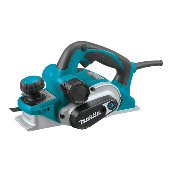
Power Planer 82mm (3-1/4")
without Plastic carrying case
Current (A)
Cycle (Hz)
KP0810C
11
50/60
10
50/60
6
50/60
6
50/60
6
50/60
=rpm
-1
Planing width
Planing depth
Shiplapping
Planer blade (re-sharpenable type)
T.C.T. Mini planer blade
Dressing stone
Elbow
Plastic carrying case
H
Continuous Rating (W)
Input
KP0810
KP0810C
850
1,050
---
---
850
1,050
850
1,050
850
1,050
KP0810
16,000
82 (3-1/4)
4 (5/32)
25 (1)
No
No
Double insulation
*2.5 (8.2)
3.2 (7.2)
W
Dimensions: mm (")
Length (L)
Width (W)
Height (H)
Max. Output (W)
Output
KP0810
500
900
500
900
500
900
500
900
500
900
KP0810C
12,000
Yes
Yes
3.3 (7.3)
PRODUCT
P 1 /11
L
290 (11-3/8)
168 (6-5/8)
176 (6-15/16)
KP0810C
1,200
1,200
1,700
1,700
1,700
Advertisement

Related Manuals for Makita KP0810


Summary of Contents for Makita KP0810
- Page 1 KP0810, KP0810C Description Power Planer 82mm (3-1/4") ONCEPT AND MAIN APPLICATIONS Model KP0810 features the following user-friendly advantages: *Left and right chip ejection for convenience *Precise planing depth setting by adjustment dial with click stops and easy-to-read scale with 0.1mm divisions *Front base with 3 chamfering grooves *Shiplapping Cuts: up to 25mm (1")
-
Page 2: Necessary Repairing Tools
1R350 Ring 60 (2pcs required) Holding the Machine when removing Bracket from Housing [2] LUBRICATION Apply Makita grease N. No.1 to the following portions designated with the black triangle to protect parts and product from unusual abrasion. Item No. Description... - Page 3 P 3 /11 epair [3] DISASSEMBLY/ASSEMBLY [3] -1. Poly V-Belt DISASSEMBLING 1) Put the machine on two 1R350's with Belt cover side up. (Fig. 2) 2) Remove Belt cover by unscrewing Pan head screw M4x18. Poly V-belt 4-241 can now be seen. (Fig. 3) Fig.
-
Page 4: Motor Section
P 4 /11 epair [3] DISASSEMBLY/ASSEMBLY [3] -2. Motor Section DISASSEMBLING 1) Remove Poly V-belt 4-241 as illustrated in Fig. 2 to Fig. 4. Note: Armature cannot be removed from Bracket complete until the Poly V-belt is removed from Pulleys. 2) Remove Rear cover by unscrewing two 4x18 Tapping screws. - Page 5 P 5 /11 epair [3] DISASSEMBLY/ASSEMBLY [3] -3. Drum and Drum Holder Section DISASSEMBLING 1) Remove Bracket complete from Housing as illustrated in Fig. 7 to Fig. 9. 2) Remove V-Pulley 4-37 from the shaft of Drum complete by turning counterclockwise with Wrench 13. (Fig. 12) Important: Wear gloves to prevent injury to be caused by the sharp edge of Drum complete.
- Page 6 P 6 /11 epair [3] DISASSEMBLY/ASSEMBLY [3] -3. Drum and Drum Holder Section (cont.) ASSEMBLING 1) Do the reverse of the disassembling steps 8) to 6). (Figs. 18 to 16) Note: Do not forget to assemble Flat washer 10 to Drum holder complete as illustrated to left in Fig. 19 before assembling Ball bearing 6900LLB.
- Page 7 Front base and Cam can now be removed from Housing. (Fig. 24) Front panel bind CT 4x12 (2 pcs) ASSEMBLING 1) Apply Makita grease N. No.1 to the portions designated in Fig. 1 on page 2. Leaf spring 2) Insert Cam through the hole of Housing from the bottom side of (2 pcs) Housing as illustrated in Fig.
- Page 8 P 8 /11 epair [3] DISASSEMBLY/ASSEMBLY [3] -5. Base section DISASSEMBLING Base can be removed from Housing by unscrewing four 4x18 Tapping screws. (Fig. 28) ASSEMBLING Important: The edge of Base on Drum holder complete side must be exactly aligned with that of Front base. 1) Place a ruler against the edge of Front base on Drum holder complete side.
- Page 9 P 9 /11 epair [3] DISASSEMBLY/ASSEMBLY [3] -7. Electrical Parts in Handle Section DISASSEMBLING For replacing the electrical parts in Handle section; Fig. 30 1) Remove Rear cover by unscrewing two 4x18 Tapping screws. (Fig. 30) Tapping screw 4x18 (2 pcs) Handle (R) Note: It is impossible to remove Handle (R) from Handle (L) without removing Rear cover.
-
Page 10: Circuit Diagram
P 10/11 ircuit diagram KP0810 Fig. D-1 Color index of lead wires' sheath *Noise Suppressor is not used for some countries. Black White *Noise suppressor (if used) Power supply cord Switch Field Carbon brush Carbon brush Power supply cord side... -
Page 11: Wiring Diagram
P 11/11 iring diagram KP0810 Fig. D-3 Handle (L) Route Field lead wires through If Noise suppressor is used these portions of Housing. put in this portion. Switch Noise suppressor (if used) Lead wire holder Housing Brush holder Route three Field lead wires under the rib, then fix two Field lead wires to Switch with Lead wire holder.
Need help?
Do you have a question about the KP0810 and is the answer not in the manual?
Questions and answers