LOVATO ELECTRIC EXP10 14 Instruction Manual
Expansion module profibus dp interface
Hide thumbs
Also See for EXP10 14:
- Instruction manual (12 pages) ,
- Installation manuals (3 pages) ,
- Installation manual (3 pages)
Advertisement
Quick Links
Download this manual
See also:
Instruction Manual
LOVATO ELECTRIC S.P.A.
24020 GORLE (BERGAMO) ITALIA
VIA DON E. MAZZA, 12
TEL. 035 4282111
FAX (Nazionale): 035 4282200
FAX (International): +39 035 4282400
L
E
E-mail info@
ovato
lectric.com
L
E
Web
www.
ovato
lectric.com
WARNING!
– Carefully read the manual before the installation or use.
– This equipment is to be installed by qualified personnel, complying to current standards, to avoid
damages or safety hazards.
– Remove the dangerous voltage from the product before any maintenance operation on it.
– Products illustrated herein are subject to alteration and changes without prior notice.
– Technical data and descriptions in the documentation are accurate, to the best of our knowledge, but
no liabilities for errors, omissions or contingencies arising therefrom are accepted.
– Clean the instrument with a soft dry cloth, do not use abrasives, liquid detergents or solvents.
INTRODUCTION
EXP expansion modules are designed and developed to enhance the functions of connectivity, I/O,
memory and analysis of the device to which it is connected.
The EXP10 14 implements the isolated PROFIBUS® serial interface. This module can be connected to a
Lovato Electric device equipped with EXP slot. The connection is done simply by plugging it into the
expansion slot of the base device. Which will automatically recognise it. The EXP parameters setup will
be done directly from the proper device menu in an easy way.
DESCRIPTION
– Compact size
– Direct plug in on the base device
– 2KVrms for 1 minute of insulation from the base module
®
– PROFIBUS
DP slave, up to 12M
– Max number of exchange bytes 18 INPUT 34 OUTPUT
– Auto Baudrate (9.600-19.200-45.450-93.750-187.500-500.000-1.5M-3M-6M-12M bps)
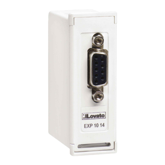
– Standard 9-pin D-sub female connector
– File .GSD download available (www.lovatoelectric.com).
LOVATO PRODUCTS COMPATIBILITY
EXP10 14 can be connected to a Lovato Electric product fitted by EXP receptacle slot. Verify the
compatibility with the following table:
BASE DEVICE
BASE DEVICE FW REV.
≥ 07
DMG800
≥ 04
DMG900 - DMG900T
WARNING!
When the EXP... module is installed on a DMG series multimeter, it is mandatory to install the
sealable terminal block covers supplied with the multimeter.
GB EXPANSION MODULE PROFIBUS
Instructions manual
I
MODULO DI ESPANSIONE INTERFACCIA PROFIBUS
Manuale operativo
EXP10 14
®
DP INTERFACE
®
DP
ATTENZIONE!!
– Leggere attentamente il manuale prima dell'utilizzo e l'installazione.
– Questi apparecchi devono essere installati da personale qualificato, nel rispetto delle vigenti normative
impiantistiche, allo scopo di evitare danni a persone o cose.
– Prima di qualsiasi intervento sull'apparecchio, togliere tensione dagli ingressi di alimentazione e dalle
uscite relè dove presenti.
– Il costruttore non si assume responsabilità in merito alla sicurezza elettrica in caso di utilizzo
improprio del dispositivo.
– I prodotti descritti in questo documento sono suscettibili in qualsiasi momento di evoluzioni o di
modifiche. Le descrizioni ed i dati a catalogo non possono pertanto avere alcun valore contrattuale.
– Pulire lo strumento con panno morbido, non usare prodotti abrasivi, detergenti liquidi o solventi.
INTRODUZIONE
I moduli di espansione EXP... sono stati progettati e sviluppati per potenziare le funzioni di connettività,
I/O, memorizzazione ed analisi dello strumento base a cui vengono collegati. In particolare il modulo
EXP10 14 realizza la funzione di interfaccia seriare isolata di tipo PROFIBUS®. Questo modulo può
essere collegato ad un apparecchio Lovato Electric provvisto di slot per EXP. La connessione avverrà
semplicemente inserendo il modulo di espansione nello strumento principale il quale ne effettuerà
automaticamente il riconoscimento.
L'impostazione dei parametri del modulo viene svolta in modo intuitivo e semplice nel menù di
configurazione presente nel dispositivo principale.
DESCRIZIONE
– Dimensioni compatte.
– Inserimento diretto nello slot di espansione dell'apparecchio.
– Isolamento da 2kVrms per 1minuto dall'apparecchio base.
®
– PROFIBUS
DP slave fino a 12M.
– Massimo numero di byte di scambio 18 INPUT 34 OUTPUT.
– Auto Baudrate (9.600-19.200-45.450-93.750-187.500-500.000-1.5M-3M-6M-12M bps)
– Connettore standard D-sub 9 poli femmina.
– Download del file .GSD disponibile (www.lovatoelectric.com).
COMPATIBILITÀ CON I PRODOTTI LOVATO
Il modulo EXP10 14 può essere abbinato ad un prodotto Lovato Electric provvisto di alloggiamento per
espansione EXP. Verificare la compatibilità secondo la seguente tabella:
APPARECCHIO BASE
REV. SW APPARECCHIO BASE
≥ 07
DMG800
≥ 04
DMG900 - DMG900T
ATTENZIONE!
Quando vengono installati i moduli EXP nei multimetri della serie DMG, è obbligatorio
montare i coprimorsetti piombabili forniti con il multimetro.
1
Advertisement

Subscribe to Our Youtube Channel
Related Manuals for LOVATO ELECTRIC EXP10 14


Summary of Contents for LOVATO ELECTRIC EXP10 14
- Page 1 LOVATO PRODUCTS COMPATIBILITY COMPATIBILITÀ CON I PRODOTTI LOVATO EXP10 14 can be connected to a Lovato Electric product fitted by EXP receptacle slot. Verify the Il modulo EXP10 14 può essere abbinato ad un prodotto Lovato Electric provvisto di alloggiamento per compatibility with the following table: espansione EXP.
-
Page 2: Measure Group
3. Remove the expansion slot cover of the Lovato product at the position in which the EXP will be plug in. 3. Rimuovere il tappo di copertura dello slot nel quale si intende inserire il modulo. 4. Insert the EXP10 14 as illustrated in the above picture. 4. Inserire l’EXP10 14 come indicato nella foto in alto. -
Page 3: Table Of Contents
MEASURE GROUP 0 POS BYTE UNIT GRUPPO DI MISURE 0 POS BYTE UNITA’ Measure group Gruppo di misura Not used Non usato L1 Phase Voltage Instantaneous 3 - 6 V/100 Tensione di fase L1 Istantanea 3 - 6 V/100 L2 Phase Voltage Instantaneous 7 - 10 V/100 Tensione di fase L2 Istantanea... -
Page 4: Gruppo Di Misura
MEASURE GROUP 6 POS BYTE UNITA’/UNIT GRUPPO DI MISURE 6 POS BYTE UNITA’ Measure group Gruppo di misura Not used Non usato L1 Voltage Thd Instantaneous 3 - 6 %/100 L1 Voltage Thd Instantaneous 3 - 6 %/100 L2 Voltage Thd Instantaneous 7 - 10 %/100 Thd Tensione L2 Istantanea... -
Page 5: L3 Phase Voltage Instantaneous
MEASURE GROUP 100 POS BYTE UNIT GRUPPO DI MISURE 100 POS BYTE UNITA’ Measure group Gruppo di misura Not used Non usato L1 Phase Voltage Instantaneous 3 - 6 V/100 Tensione di fase L1 Istantanea 3 - 6 V/100 L2 Phase Voltage Instantaneous 7 - 10 V/100 Tensione di fase L2 Istantanea... -
Page 6: Not Used
MEASURE GROUP 130 POS BYTE UNIT GRUPPO DI MISURE 130 POS BYTE UNITA’ Measure group Gruppo di misura Not used Non usato 2. Harmonic L1 Voltage 3- 4 2. Armonica Tensione L1 3- 4 3. Harmonic L1 Voltage 5- 6 3. -
Page 7: Not Used
MEASURE GROUP 133 (DMG900 only) POS BYTE UNIT GRUPPO DI MISURE 133 (solo DMG900) POS BYTE UNITA’ Measure group Gruppo di misura Not used Non usato 50. Harmonic L1 Voltage 3- 4 50. Armonica Tensione L1 3- 4 51. Harmonic L1 Voltage 5- 6 51. -
Page 8: Not Used
MEASURE GROUP 188 POS BYTE UNIT GRUPPO DI MISURE 188 POS BYTE UNITA’ Measure group Gruppo di misura Not used Non usato Active Energy Imp. Tariff A 3 - 10 Kwh/100ƒ Tariffa A Energia Attiva Importata 3 - 10 Kwh/100 Active Energy Exp. -
Page 9: Not Used
MEASURE GROUP 206 POS BYTE UNIT GRUPPO DI MISURE 206 POS BYTE UNITA’ Measure group Gruppo di misura Not used Non usato Counter 1 3 - 6 Contatore 1 3 - 6 Counter 2 7 - 10 Contatore 2 7 - 10 Counter 3 11- 14 Contatore 3... - Page 10 TARIFF SELECTION (GROUP 252) IMPOSTAZIONE TARIFFE (GRUPPO 252) – It is possible to selct the active tariff, the possible range is: – E’ possibile selezionare la tariffa, i valori impostabili sono: • DMG 800: from 1 to 4 • DMG 800: da 1 a 4 •...
- Page 11 PINOUT PINOUT ® PROFIBUS CONNETTORE ® CONNECTOR (DB9F) PROFIBUS FUCTION FUNZIONE B-Line B-Line GND BUS(isolated) GND BUS(isolata) +5V BUS(output isolated,100mA max) +5V BUS(output isolata,100mA max) A-Line A-Line TECHNICAL CHARACTERISTICS CARATTERISTICHE TECNICHE Supply Alimentazione Supply voltage Tensione alimentazione (supplied by base device) (fornita dall’apparecchio principale) Consumption 190mA...
Need help?
Do you have a question about the EXP10 14 and is the answer not in the manual?
Questions and answers