Table of Contents
Advertisement
Quick Links
Advertisement
Table of Contents

Related Manuals for IFM JN2101


Summary of Contents for IFM JN2101
- Page 1 Device manual Inclination sensor 2 axes JN2101 from firmware 2.5.0...
-
Page 2: Table Of Contents
Inclination sensor JN Contents 1 Preliminary note ..........4 1.1 Symbols used. - Page 3 Inclination sensor JN 9.8 MEMS self-test (SDO index 4004h) ......21 9.9 Temperature of the measuring cell (SDO index 4080h) ....21 9.10 Inclination values longitudinal and lateral (SDO index 6010h and SDO index 6020h) .
-
Page 4: Preliminary Note
Inclination sensor JN 1 Preliminary note Technical data, approvals, accessories and further information at www.ifm.com. This document applies to the device of type „inclination sensor“ (art. no.: JN2100). It is part of the device. This document is intended for specialists. These specialists are people who are... -
Page 5: Functions And Features
Inclination sensor JN 3 Functions and features The 2-axis inclination sensor with CANopen interface enables angle levelling and position detection of mobile machines. Typical applications are, for example, the position detection of access platforms, levelling of mobile cranes or set-up of mobile machines. Properties: ●... -
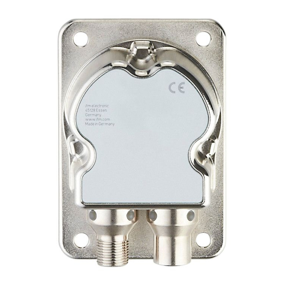
Page 6: Scale Drawing
Inclination sensor JN 5 Scale drawing M12 x1 M12 x1 6 Electrical connection The inclination sensors are fitted with two round 5-pole M12 connectors (A-coded). The pin connection corresponds to the CANopen specification CiA DR-303-1. 1: CAN_SHLD CAN shield 2: CAN_V+ Supply voltage 24 V DC (+U 3: CAN_GND Ground 4: CAN_H High bus cable... -
Page 7: Canopen Interface
Inclination sensor JN 7 CANopen interface The inclination sensors have a standardised CANopen interface to CiA DS-301 and a device profile to CiA DSP-410. All measured values and parameters can be accessed via the object directory (OD). The individual configuration can be saved in the internal permanent memory (flash). -
Page 8: Nmt Start-Up (Od Index 1F80H)
Inclination sensor JN The master or network manager can request the sensor via NMT messages to change the state accordingly. This allows almost complete separation of redundant or faulty sensors from the bus. 7.3 NMT start-up (OD index 1F80h) The sensor has a selectable start performance. The following three options can be selected under the index 1F80h: 7.3.1 Slave Only (default) (OD index 1F80h = 0) The sensor starts in the pre-operational state (0x00h). - Page 9 Inclination sensor JN Inclination value longitudinal Inclination value lateral (X axis) (y axis) OD index: 6010h OD index: 6020h The second transmit process data object TPDO1 contains the inclination values as 32-bit values. Byte 0 to byte 3 Byte 4 to byte 7 Inclination value longitudinal Inclination value lateral (X axis)
-
Page 10: Object Directory (Od)
Pre-defined error field Number of error entries 1...50 Error code (oldest error at highest index) 1005h COB ID sync message 1008h Product designation const VSTR JN2101 1009h Hardware version const VSTR X.Y.Z 100Ah Software version ("XYY") const VSTR X.Y.Z 100C h... - Page 11 Inclination sensor JN Index Sub- Name (parameter) Type Default value Autosave index (factory set) / Reset 1029h Error behaviour object Number of error classes Error behaviour 1200h Server SDO parameter Highest supported sub-index COB ID client to server 600h + node ID COB ID server to client 580h + node ID 1800h...
-
Page 12: Communication Parameters (To Cia Ds-301)
Inclination sensor JN Index Sub- Name (parameter) Type Default value Autosave index (factory set) / Reset 1A01h Transmit PDO1 mapping parameter (fixed mapping) Highest supported sub-index Inclination value longitudinal 61100020h (X axis) Inclination value lateral 61200020h (Y axis) 1F80h NMT start-up Slave only Start-up capable device NMT start command... - Page 13 Inclination sensor JN The oldest error is in the highest available sub-index and is the first to be removed from the list in the case of more than 50 errors. If an error occurs, a new error entry is added to the error field (OD index 1003h) and also communicated via an EMCY message.
-
Page 14: Service Data Object (Sdo) Mapping
Inclination sensor JN 7.6 Service data object (SDO) mapping 7.6.1 System settings 0x2000 - 0x203F Sub- Type Value Unit Reset index index 0x2000 Node ID 0x2001 Baud rate Kbit 0x2002 Flag to reset the sensor Flag = 1 sensor reset 7.6.2 Applicative 0x2040 - 0x207F Sub- Type... -
Page 15: System Settings 0X4000 - 0X403F
Inclination sensor JN Sub- Type Value Unit Reset index index 0x3000 Programming key 0x4001 ASCII Configuration 1 (Manufacturer only) 7.6.3 System settings 0x4000 - 0x403F Sub- Type Value Unit Reset index index 0x4004 MEMS self-test Number sub-indices 0x4004 0x01 Flag to activate the self-test →... -
Page 16: Angle Definition (Sdo Index 2044H)
Inclination sensor JN Sub- Type Value Unit Auto- index index save / Reset 0x6120 Integer Lateral Y axis Angle [°] 0x6121 Slope lateral32 lateral operating parameter 8 Angle definition (SDO index 2044h) To be able to adapt the inclination sensor to the different applications as easily as possible, the measured inclination information is converted into different angle indications. -
Page 17: Gimbal Angle X (Sdo Index 2044 = 2)
Inclination sensor JN The current sensor orientation is determined by two successive rotations from the horizontal position. The "inclination value longitudinal" indicates the angle [°] at which the Z axis of the sensor is inclined. The "inclination value lateral" corresponds to the angle [°] at which the sensor was then rotated about the (inclined) Z axis. -
Page 18: Gimbal Angle Y (Sdo Index 2044 = 3)
Inclination sensor JN be detected by the inclination sensor. In this condition the "inclination value lateral" is insignificant. In practice, the "inclination value lateral" will vary very strongly when it is close to this condition even if there is only little movement. 8.4 Gimbal angle Y (SDO index 2044 = 3) This setting corresponds to the setting described in 8.3 with the difference that the order of the two rotations is now inverted. -
Page 19: Other Sensor Functions
→ Chapter 11.2 COB IDs. The inclination sensor from ifm is delivered with the node ID 10 and a baud rate of 125 Kbits/s. The following baud rates [kBit/s] are supported: 10, 20, 50, 125, 250, 500, 800 and 1000. -
Page 20: Set Teach (Sdo Index 2042H)
Inclination sensor JN 9.5 Set teach (SDO index 2042h) Should it not be possible to integrate the inclination sensor into the measured object so that the coordinate system of the sensor and object match, the teach function enables the creation of a new reference system. The new reference system X is defined so that its Z direction corresponds... -
Page 21: Quadrant Correction (Sdo Index 2040H)
-29.5° -30° 0° 9.6 Quadrant correction (SDO index 2040h) Quadrant correction means for JN2101 only an extension of the lateral Euler angle to the measuring ranges 180° (corresponds to 2040h = 1) or 0...360° ± (corresponds to 2040h = 2). -
Page 22: Inclination Values Longitudinal And Lateral (Sdo Index 6010H And Sdo Index 6020H)
Inclination sensor JN 9.10 Inclination values longitudinal and lateral (SDO index 6010h and SDO index 6020h) The current angle values of the inclination axes can be accessed via SDO access to the object directory (in every device state) and via TPDO. The conversion of the 100-fold, signed 16-bit inclination value (two's complement) is as follows: Value of the SDO index 6010h = -2370, thus the angle is -2370 / 100 = -23.70°... -
Page 23: Parameter (Connection Set) Handling
Inclination sensor JN 10 Parameter (connection set) handling The CAN identifiers (COB IDs) of the communication objects are determined according to the pre-defined connection set with every reset (communication, application and hardware reset) depending on the set node ID (SDO index 2000h). Always make sure that the current parameters (connection set) always match the current node ID. -
Page 24: Emergency Messages
Inclination sensor JN 11 Emergency messages Every inclination sensor supports EMCY messages which are transmitted in the event of sensor, temperature, hardware or guarding errors. If one of these errors occurs, the error register (OD index 1001h) and the pre- defined error field (OD index 1003h) are updated. -
Page 25: Cob Ids
Inclination sensor JN Heartbeat function has a considerable influence on the bus load of the CANopen network - but generates a bus load which is only half as high as node guarding / life guarding. 11.2 COB IDs The CAN identifiers of the communication objects are determined according to the pre-defined connection set with every reset (communication, application and hardware reset) depending on the set node ID (SDO index 2000h). -
Page 26: Maintenance, Repair And Disposal
12 Maintenance, repair and disposal The unit is maintenance-free. ► Dispose of the device in accordance with the national environmental regulations. 13 Approvals/standards The CE declarations of conformity and approvals can be found at www.ifm.com. 14 Factory setting Sub- Type Value...
Need help?
Do you have a question about the JN2101 and is the answer not in the manual?
Questions and answers