
Related Manuals for Emerson Rosemount 1495


Summary of Contents for Emerson Rosemount 1495
- Page 1 Quick Start Guide 00825-0100-4792, Rev. BB February 2014 Rosemount 1495 Orifice Plate Rosemount 1496 Orifice Flange Union...
- Page 2 February 2014 Quick Start Guide NOTICE This installation guide provides basic guidelines for Rosemount 1495 Conditioning Orifice Plate. It does not provide instructions for configuration, diagnostics, maintenance, service, troubleshooting, Explosion-proof, Flame-Proof, or intrinsically safe (I.S.) installations. Refer to the 1495 reference manual (document number 00809-0100-4792) for more instruction.
- Page 3 To obtain published accuracy for a 1495 Orifice Plate, sufficient straight run is required to produce a fully developed flow profile. Please see Appendix B of the Rosemount 1495 Orifice Plate Manual (00809-0100-4792) for a list of required straight pipe recommendations based on ISO 5167, AGA Report No. 3, and ASME MFC 3M Standards.
- Page 4 LO instrument line before running down to the transmitter Step 3: Primary element installation Note For the 1496 Flange Union refer to the Rosemount 1495 Orifice Plate reference manual (document number 00809-0100-4792). Use the following steps to install the 1495 Orifice Plate (paddle or universal plate style).
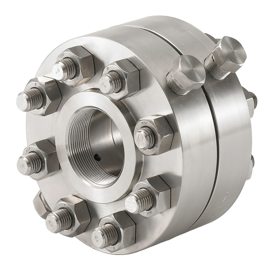
- Page 5 Center the plate in the pipe I.D. h. Release the flange union by turning the jackscrews counter-clockwise. i. Replace the studs. j. Tighten studs in a star pattern. Figure 1. Rosemount 1495 installation Stud Pipe Section Jackscrew...
- Page 6 February 2014 Quick Start Guide Figure 2. Rosemount 1495 with plate holder (PH) installation Stud Pipe Section 1495 Nuts Nuts Jackscrew Jackscrew Transmitter (1) The installation drawings applies when using the Rosemount 3051S, Rosemount 3051C, and Rosemount 3095MV transmitter. See the following documents for quick installation instruction of the transmitters.
- Page 7 Rosemount website at www.rosemount.com. A hard copy may be obtained by contacting our local sales office. European Pressure Equipment Directive (PED) (97/23/EC) Rosemount 1495 Orifice Plate — Sound Engineering Practice (SEP) Pressure Transmitter — See appropriate Pressure Transmitter QIG...
- Page 8 © 2014 Rosemount Inc. All rights reserved. All marks property of owner. Instrument Co., Limited The Emerson logo is a trade mark and service mark of Emerson Electric Co No. 6 North Street, Hepingli, Rosemount and the Rosemount logotype are registered trademarks of Rosemount Dong Cheng District Inc.
Need help?
Do you have a question about the Rosemount 1495 and is the answer not in the manual?
Questions and answers