Advertisement
Quick Links
+050001531 - rel. 1.1 del 09.03.2010
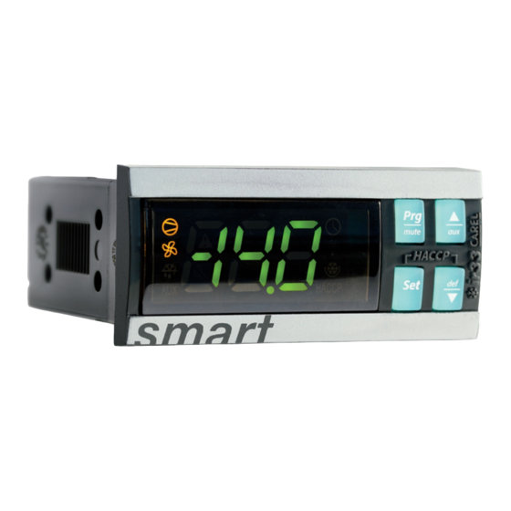
ir33 smart
- IR33C7HB0E electronic controller for normal and low temperature ventilated refrigeration units
•
Electronic controller for normal and low temperature ventilated refrigeration units
• 115/230 Vac switching power supply
• 16 A compressor relay
• Management of NTC (-50 to +90°C) and PTC (-50 to +150°C) sensors
• Simple and intuitive installation and confi guration
• 6 pre-loaded confi gurations for the most common refrigeration applications
• HACCP reports
• Real time clock
READ ME NOW!!!
With reference to the label on the rear of the instrument and the required application
1. Check that power supply, probes and loads (compressor, heaters, etc.) are suitable for the
instrument.
2. Fasten the instrument to the panel as shown in the following fi gure.
3. Make all the required electrical connections.
4. Power up the unit.
5. After around 2 seconds, if the instrument displays the temperature read by the probes connected
to the device, go directly to point 7. If nothing is displayed or an alarm is signalled (alarm codes on
the display), power down, check the connections and the power supply and go to point 6.
6. Power the unit up again. If the instrument now correctly displays the temperature, go to point 7. If,
on the other hand, the problem described in point 5 is repeated, see the table "Alarms and signals:
display, buzzer and relay" to identify the cause of the problem.
7. ir33 smart is now ready to be confi gured. For correct confi guration based on the required
application, see the section "How to select and load a confi guration".
Dimensions (mm)
70,5
76,2
79
80,6
56,5
65
Wall mounting ir33
1
2
Wall mounting by two plastic brackets sliding in from side
Wiring diagram
N
R1
R3
R4
L
EN60730-1
12 (2) A
UL 873
12A 5FLA
30LRA
POWER
-10T60
SUPPLY
R1
R2
L
N
1
2
1
N
L
PROBES
DI DI
Optional connections
IROPZ48500
Serial board interface RS485
1
2
IMPORTANT: separate the probe and digital input cables from the
NO POWER
cables to inductive loads and power cables to avoid electromagnetic
& SIGNAL
CABLES
disturbance. Never run power cables (including electrical panel
TOGETHER
READ CAREFULLY IN THE TEXT!
cables) and signal cables in the same conduits.
How to select and load a user confi guration
Step Action
Effect
Meaning
After 2 seconds the
'bn0' is the current confi guration. (Standard CAREL
Switch the instrument on
1
display shows the
when fi rst switched on or other user confi guration,
while holding
message 'bn0'
if loaded)
The display shows the
Select the required confi guration
def
2
messages 'bn1', 'bn2',
Press
or
(refer to the following table)
'bn3', 'bn4', 'bn5', 'bn6'
aux
The display shows "Std"
The user confi guration selected in point 2 will be
3
Press
Set
for 1 sec
loaded
This procedure can only be performed once: the most suitable confi guration for the application, once
loaded, will remain active the next time the instrument is started.
When switching on the fi rst time, bn0 corresponds to the Carel standard (default confi guration). The
procedure for loading one of the user confi gurations involves copying one of the sets of parameters
(bn1,...,bn6) to bn0. bn0 therefore always corresponds to the last confi guration loaded.
Confi gurations
ir33 SMART is loaded with 6 default confi gurations (sets of parameters). Each confi guration identifi es
a specifi c refrigeration application, and can be identifi ed simply by the index (bn*) when switching the
instrument on.
Index
Application
Op. T. range Inputs
Normal temperature ventilated refrigeration
bn1
2T10°C
units with heater defrost (timed)
Normal temperature ventilated refrigeration
bn2
units with heater defrost (by temperature)
2T10°C
and light control
Normal or low temperature ventilated refrige-
-20T-14°C
bn3
ration units with heater defrost
2T10 °C
(by temperature) and light control
Normal temperature ventilated refrigeration
bn4
units with heater defrost (with two evapora-
2T10°C
tors, by temperature)
Normal or low temperature ventilated
-20T-14°C
bn5
refrigeration units with heater defrost (with
2T10 °C
two evaporators, by temperature)
bn6
Standard CAREL (default confi g.)
-50T90 °C
bn1: normal temperature (+2T10 °C) ventilated refrigeration units
with heater defrost (timed) -
Temperature control
Compressor
DIRECT MODE
NO POWER
& SIGNAL
CABLES
TOGETHER
READ CAREFULLY IN THE TEXT!
Set point
Inputs
Room probe
Compressor
Outputs
Defrost heater
Evaporator fan
Name
Main parameters
(type F)
AL (*)
AH (*)
(*) alarm thresholds AL & AH absolute. Relay R4 is not used.
bn2: normal temperature (+2T10 °C) ventilated refrigeration units
with heater defrost (by temperature) and light control
Temperature range: 2T10 °C
Temperature control
Compressor
DIRECT MODE
Set point
*: short-circuit terminals 10 and 11 if the door switch is
not used
dima di foratura
drilling template
Room probe
71x29 mm
Inputs
Defrost probe
Door switch
Compressor
Defrost heater
Outputs
Evaporator fan
Light
Name
Main parameters
(type F)
AL (*)
AH (*)
R2
R3
R4
(*) absolute alarm thresholds
8 (4) A
8 (4) A
8 (4) A
8A 2FLA
8A 2FLA
8A 2FLA
bn3: normal (+2T10 °C) or low temperature (-20T-14 °C) ventilated
12LRA
12LRA
12LRA
SERIAL BOARD & KEY
refrigeration units with heater defrost (by temperature) and light control
Temperature range -20T-14 °C & +2T10 °C
tLAN interface
Temperature control
Compressor
2
DIRECT MODE
Set point
*: short-circuit terminals 10 and 11 if the door switch is not used
IROPZKEY**
Programming key
Room probe
Inputs
Defrost probe
Door switch
Compressor
Defrost heater
Outputs
IROPZDSP00
Evaporator fan
Display interface option
Light
Name
Main parameters
(type F)
AL (*)
AH (*)
(*) absolute alarm thresholds
bn4: normal temperature ventilated refrigeration units (+2T10 °C)
with heater defrost (by temperature) and two evaporators
Temperature range +2T10 °C
Temperature control
Compressor
DIRECT MODE
Set point
Relay outputs
Room probe
Compressor
Inputs
Defrost probe 2a
Defrost probe 2b
NTC room
Defrost
Compressor
Fans
Defrost heater 1
Compressor
Outputs
NTC room
Defrost heater 2
Defrost
NTC evaporator
Evaporator fan
Fans
DI door switch
Name
Light
Compressor
NTC room
Defrost
NTC evaporator
Fans
DI door switch
Light
Compressor
NTC room
Main parameters
Defrost
NTC evaporator 1
(type F)
Evap fans 1
NTC evaporator 2
Evap fans 2
AL (*)
Compressor
AH (*)
NTC room
Defrost
NTC evaporator 1
Evap fans 1
NTC evaporator 2
Evap fans 2
confi gurable
confi gurable
(*) absolute alarm thresholds
Temperature range: 2T10 °C
Connection diagram
N
R3
R4
L
POWER
SUPPLY
R1
R2
L
N
1
Temp. °C
115/230 V~
rd
N
L
50mA~ max
PROBE
NTC 1
R1: 16 A relay
R3: 8 A relay
R2: 8 A relay
Type
Description
Default value
St
Set point
4 °C
CtL
rd
Control differential (hysteresis)
2 °C
dl
Interval between defrosts
8 hours
dEF
dP1
Maximum evap. defrost duration
30 min
Minimum temperature alarm
-30 °C
Maximum temperature alarm
30 °C
ALM
Ad
Temperature alarm delay
30 min
F0
Fan management
0
FAn
Fd
Fans off after dripping
0 min
Connection diagram
R3
R4
POWER
SUPPLY
R1
R2
L
N
Temp. °C
1
2
rd
115/230 V~
N
L
50mA~ max
PROBES
NTC 1
NTC 2
Digital input DI1
R1: 16 A relay
R3: 8 A relay
R2: 8 A relay
R4: 8 A relay
Type
Description
Default value
St
Set point
2 °C
CtL
rd
Control differential (hysteresis)
2 °C
dl
Interval between defrosts
6 hours
dt1
Evaporator end defrost temperature
4 °C
dEF
dd
Dripping time
2 min
d/1
Defrost probe 1 reading
-
Minimum temperature alarm
-30 °C
Maximum temperature alarm
30 °C
ALM
Ad
Temperature alarm delay
30 min
F0
Fan management
0
F1
Fan on temperature
5 °C
FAn
Fd
Fans off after dripping
2 min
Connection diagram
R3
R4
POWER
SUPPLY
R1
R2
L
N
1
Temp. °C
rd
115/230 V~
N
L
50mA~ max
PROBES
NTC 1
NTC 2
Digital input DI1
R1: 16 A relay
R3: 8 A relay
R2: 8 A relay
R4: 8 A relay
Type
Description
Default value
St
Set point
-14 °C
CtL
rd
Control differential (hysteresis)
2 °C
dl
Interval between defrosts
6 hours
dt1
Evaporator end defrost temperature
4 °C
dEF
dd
Dripping time
2 min
d/1
Defrost probe 1 reading
-
Minimum temperature alarm
-50 °C
Maximum temperature alarm
30 °C
ALM
Ad
Temperature alarm delay
30 min
F0
Fan management
0
F1
Fan on temperature
5 °C
FAn
Fd
Fans off after dripping
2 min
Connection diagram
R3
R4
POWER
SUPPLY
R1
R2
L
N
1
2a
Temp. °C
115/230 V~
rd
N
L
50mA~ max
PROBES
NTC 1
NTC 2
NTC 3
R1: 2 HP relay
R3: 8 A relay
R4: 8 A relay
R2: 8 A relay
Type
Description
Default value
St
Set point
2 °C
CtL
rd
Control delta
2 °C
dl
Interval between defrosts
6 hours
dt1
Evaporator end defrost temperature
4 °C
dt2
AUX evap. end defrost temperature
4 °C
dEF
dd
Dripping time
2 min
d/1
Defrost probe 1 reading
-
d/2
Defrost probe 2 reading
-
Minimum temperature alarm
-30 °C
Maximum temperature alarm
30 °C
ALM
Ad
Temperature alarm delay
30 min
F0
Fan management
0
F1
Fan on temperature
5 °C
FAn
Fd
Fans off after dripping
2 min
bn5: normal (+2T10 °C) or low temp. (-20T-14 °C) ventilated refrigera-
tion units with heater defrost (by temperature) & two evaporators
Temperature range -20T-14 °C & +2T10 °C
Temperature control
Compressor
DIRECT MODE
Temp. °C
rd
Set point
Room probe
NTC 1
Inputs
Defrost probe 2a
NTC 2
Defrost probe 2b
NTC 3
Compressor
R1: 2 HP relay
Defrost heater 1
R3: 8 A relay
Outputs
Defrost heater 2
R4: 8 A relay
Evaporator fan
R2: 8 A relay
Name
Type
Description
St
Set point
CtL
rd
Control delta
dl
Interval between defrosts
dt1
Evaporator end defrost temperature
dt2
AUX evaporator end defrost temp.
dEF
dd
Dripping time
Main parameters
d/1
Defrost probe 1 reading
(type F)
d/2
Defrost probe 2 reading
AL (*)
Minimum temperature alarm
AH (*)
Maximum temperature alarm
ALM
Ad
Temperature alarm delay
F0
Fan management
F1
Fan on temperature
FAn
Fd
Fans off after dripping
(*) absolute alarm thresholds
bn6: standard CAREL (default confi guration)
Connection diagram
R3
R4
DOOR
SWITCH
DI
R1
R2
N
L
Name Type
Description
St
Set point
rd
Control delta
rt
Temperature monitoring interval
CtL
rH
Maximum temperature read
rL
Minimum temperature read
dl
Interval between defrosts
dt1
Evaporator end defrost temperature
dt2
AUX evaporator end defrost temp.
dP1
Maximum evaporator defrost duration
Main parameters
dP2
Maximum evaporator defrost duration
(type F)
dEF
dd
Dripping time
Alarm bypass time after defrost and/or door
d8
open
d/1
Defrost probe 1 reading
d/2
Defrost probe 2 reading
AL
Minimum temperature alarm
AH
Maximum temperature alarm
ALM
Ad
Temperature alarm delay
F1
Fan on temperature
FAn
Fd
Fans off after dripping
Indications on the display
When fl ashing, the signals on the display indicate a request that cannot be implemented until the delay
timers have expired.
Icon Function
ON
OFF
COMPRESS.
compressor on
compress. off
DOOR
2
FAN
fan on
fan off
SWITCH
DI
DEFROST
defrost in progress
no defrost call
AUX auxiliary output
AUX auxiliary output not
AUX
active
active
delayed external alarm
ALARM
(before the time "A7"has
no alarm present
elapsed)
if at least one timed
no timed defrost has
CLOCK
defrost has been set
been set
light auxiliary output
light auxiliary output not
LIGHT
active
active
SERVICE
no malfunction
function enabled (HA
HACCP
function not enabled
and/or HF)
CONT. CYCLE function activated
function not activated
Buttons on the keypad
But. Pressing the button alone
Pressing together with other buttons
• if pressed for more than
• if pressed with SET for more
5 s, accesses the menu
than 5s, accesses the menu
for setting the type F
for setting type C parameters
parameters (frequent)
(confi guration) or downloa-
• in the event of alarms:
ding the parameters
mutes the audible alarm
• if pressed together with UP/
(buzzer) and deactivates
AUX for more than 5s resets
the alarm relay
any alarms with manual reset
if pressed for more than 1
• if pressed together with DOWN/DEF for more than 5s, activates/deactiva-
s, activates /deactivates the
tes the continuous cycle
aux
auxiliary output
• if pressed with SET for more than 5s starts the report printing procedure
(function available but to be implemented)
• if pressed with PRG/MUTE for more than 5s, resets any alarms with
manual reset
2b
if pressed for more than 5
• if pressed together with UP/AUX for more than 5s activates/deactivates
def
s, activates /deactivates a
the continuous cycle
manual defrost
• if pressed for more than 1 s with SEL, displays a submenu with the
HACCP alarm parameters (HA, HAn, HF, HFn)
if pressed for more than 1
• if pressed with PRG/MUTE for more than 5s, accesses the menu for setting
Set
s, displays and/or sets the
type C parameters (confi guration) or downloading the parameters
set point
• if pressed for more than 1 s with DOWN/DEF, displays a submenu with the
HACCP alarm parameters (HA, HAn, HF, HFn)
• if pressed with UP/AUX for more than 5s starts the report printing procedu-
re (function available but to be implemented)
How to set the set point
Step Action
Effect
After 2 seconds the display will show
1
Press
Set
for 2 seconds
the current set point
The value on the display will increase
def
2
Press
or
or decrease
aux
The controller will show the temp.read by
3
Press
Set
the probes again
Another way of changing the set point is to set parameter "St" (see the tables below)
Connection diagram
R3
R4
POWER
SUPPLY
R1
R2
L
N
1
2a
2b
115/230 V~
N
L
50mA~ max
PROBES
Default value
-14 °C
2 °C
6 hours
4 °C
4 °C
2 min
-
-
-50 °C
30 °C
30 min
0
5 °C
2 min
N
L
POWER
SUPPLY
L
N
1
2
1
2
115/230 V~
50mA~ max
PROBES
DI DI
Default value
-14 °C
2 °C
-
-
-
8 hours
4 °C
4 °C
30 min
30 min
2 min
1 hour
-
-
0 °C
0 °C
120 min
5 °C
1 min
Normal operation
Startup
Flashing
compress. call
fan call
defrost call
anti-sweat heater
function active
alarms in norm.
operation (e.g. high/low
temp.) or immediate or
delayed ext. alarm from
digital input
ON if Real-
clock alarm
Time Clock
present
anti-sweat heater
function active
malfunction (e.g.
EEPROM error or faulty
probes)
HACCP alarm saved
function called
Start-up: if pressed
Automatic address as-
for more than 5 s at
signment: if pressed
start-up activates the
for more than 1 s
RESET procedure
enters the automatic
serial address assign-
ment procedure
Meaning
This the currently active control
set point
Set the desired value
The set point is modifi ed and
saved
Advertisement

Related Manuals for Carel IR33C7HB0E


Summary of Contents for Carel IR33C7HB0E
- Page 1 • if pressed together with UP/ ment procedure When switching on the fi rst time, bn0 corresponds to the Carel standard (default confi guration). The (buzzer) and deactivates AUX for more than 5s resets Compressor procedure for loading one of the user confi...
- Page 2 CAREL accepts no liability in such cases. The customer must use the product only in the manner described in the documentation and Sunday; 11 = every day. relating to the product.The liability of CAREL in relation to its products is specifi ed in the CAREL general contract conditions, available on the website www.carel.com and/or by specifi c agreements with customers.
Need help?
Do you have a question about the IR33C7HB0E and is the answer not in the manual?
Questions and answers