
Related Manuals for Carel ir33 Universale


Summary of Contents for Carel ir33 Universale
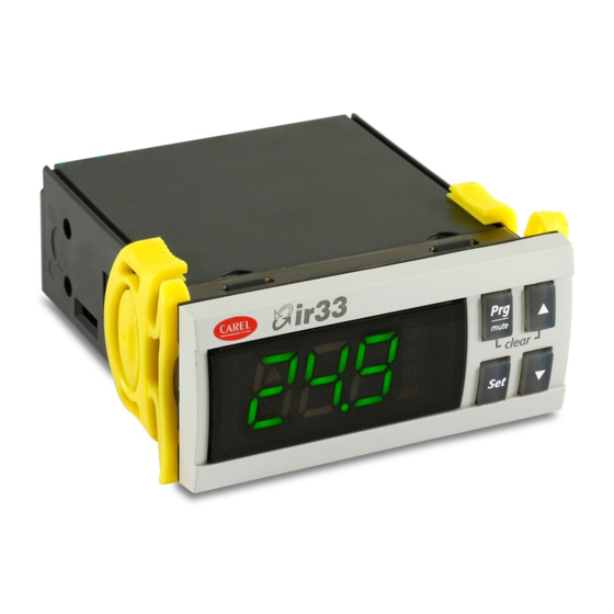
- Page 1 Universale electronic control User manual I n t e g r a t e d C o n t r o l S o l u t i o n s & E n e r g y S a v i n g s...
- Page 3 The technical specifi cations shown in the manual may be changed without prior warning. The liability of CAREL in relation to its products is specifi ed in the CAREL general contract conditions, available on the website www.carel.com and/or by specifi c agreements with customers; specifi cally, to the extent where allowed...
-
Page 5: Table Of Contents
Content 1. INTRODUCTION Models ......................7 Functions and main characteristics ............8 2. INSTALLATION 2.1 IR33: panel mounting and dimensions ..........10 2.2 DIN rail mounting and dimensions ............11 2.3 IR33/DN33 with temperature inputs - wiring diagrams ....... 12 2.4 IR33/DN33 Universale with universal inputs - wiring diagrams .. -
Page 7: Introduction
Max range -199 to 800 on models with temperature inputs only and M the 24 Vac/24Vdc 4 to 20 mA Max range -199 to 800 power supply on models with universal inputs. Tab. 1.b ir33 universale +030220801 - rel. 2.1 - 21.06.2011... -
Page 8: Functions And Main Characteristics
Starting fi rmware revision 2.0, IR33 Universale can manage two circuits the testing phase. with independent PID control. New software functions have also been introduced, such as speed-up, cut-off and forcing the output from digital input, which can be selected for each output. - Page 9 ON/OFF outputs are required for the control functions or alarms. Fig. 1.h ir33 universale +030220801 - rel. 2.1 - 21.06.2011...
-
Page 10: Installation
IR33 - optional connections Temperature inputs Universal inputs Chiave di programmazione Interfaccia scheda seriale RS485 Interfaccia scheda seriale RS485 Chiave di programmazione Programming key Serial board interface RS485 Programming key Serial board interface RS485 ir33 universale +030220801 - rel. 2.1 - 21.06.2011... -
Page 11: Din Rail Mounting And Dimensions
2.2.1 DN33 - Temperature inputs 2.2.2 DN33 - Universal inputs 2.2.3 DN33 - optional connections Interfaccia seriale RS485. Serial board RS485. Interfaccia seriale RS485 Serial board RS485 Chiave di programmazione Programming key ir33 universale +030220801 - rel. 2.1 - 21.06.2011... -
Page 12: Ir33/Dn33 With Temperature Inputs - Wiring Diagrams
8A 2FLA UL 873 8A 2FLA 0...10 V Relays 12LRA 12LRA + 0-10 Vdc SERIAL and KEY SERIAL and KEY 10 11 12 10 11 12 POWER POWER DI1 DI2 SUPPLY SUPPLY ir33 universale +030220801 - rel. 2.1 - 21.06.2011... - Page 13 PWM or 0 to 10 Vdc analogue output reference Y1/Y2/Y3/Y4 PWM or 0 to 10 Vdc analogue output signal C/NC/NO Common/Normally closed/Normally open (relay output) B1/B2 Probe 1/Probe 2 DI1/DI2 Digital input 1/ Digital input 2 ir33 universale +030220801 - rel. 2.1 - 21.06.2011...
-
Page 14: Ir33/Dn33 Universale With Universal Inputs - Wiring Diagrams
PWM or 0 to 10 Vdc analogue output signal C/NC/NO Common/Normally closed/Normally open (relay output) -B1, +B1, B1 / -B2, +B2, B2 Probe 1/Probe 2 DI1/DI2 Digital input 1/ Digital input 2 ir33 universale +030220801 - rel. 2.1 - 21.06.2011... -
Page 15: Ir33/Dn33 Universale With Universal Inputs - Probe Connections
- make sure the wire is stripped for 8-10 mm; - use a fl at-head screwdriver to press the orange locking device; - insert the wire in the hole underneath; - release the orange locking device. ir33 universale +030220801 - rel. 2.1 - 21.06.2011... -
Page 16: Connection Diagrams
G0). This allows just one transformer to be used. -B2 +B2 B2 +12 V DI1 GND -B1 +B1 B1 +5 V AC 24 V/ DC 24 V 450 mA MAX 230 Vac 24 Vac Fig. 2.c ir33 universale +030220801 - rel. 2.1 - 21.06.2011... -
Page 17: Installation
Case 2: a series of controllers connected in a network powered by diff erent transformers (G0 not earthed). Typical application for multiple controllers in diff erent electrical panels. 230 Vac 230 Vac 230 Vac 24 Vac 24 Vac 24 Vac Fig. 2.e ir33 universale +030220801 - rel. 2.1 - 21.06.2011... -
Page 18: Programming Key
Other signals or the fl ashing of the LED indicates that problems have occurred: refer to the table; 4. at the end of the operation, release the button, after a few seconds the LED goes OFF; 5. remove the key from the controller. ir33 universale +030220801 - rel. 2.1 - 21.06.2011... -
Page 19: User Interface
The user can select the standard display by suitably setting parameter c52, or by pressing (DOWN) to select one of the possible options (b1, b2, di1, di2, St1, St2) and confi rming by pressing Set. See paragraph 3.4.11. ir33 universale +030220801 - rel. 2.1 - 21.06.2011... -
Page 20: Keypad
St2; • press until reaching the required value; • press Set to confi rm the new value of St2; • the display returns to the standard view. Fig. 3.e Fig. 3.d ir33 universale +030220801 - rel. 2.1 - 21.06.2011... -
Page 21: Setting The Current Date/Time And The On/Off Times
5. To return to the list of main parameters, press 6. Select and modify parameter toF together with the corresponding hour and minutes, repeating the sequence from point 2 to 5. ir33 universale +030220801 - rel. 2.1 - 21.06.2011... - Page 22 5 seconds. Termination of the operating cycle is indicated by the message “StP” (stop). 3.4.10 Auto-Tuning activation See the chapter on Control. Auto-Tuning is incompatible with independent operation (c19=7). Fig. 3.l ir33 universale +030220801 - rel. 2.1 - 21.06.2011...
-
Page 23: Using The Remote Control (Accessory)
The buttons can be divided into three groups, based on their functions: • Enabling/disabling the use of the remote control (Fig. 1); • Remote simulation of the controller keypad (Fig. 2); • Direct display/editing of the most common parameters (Fig. 3). ir33 universale +030220801 - rel. 2.1 - 21.06.2011... - Page 24 In Levels 1 and Level 2, the buttons repeat the corresponding functions on the controller keypad. In this way, all the controller parameters can be displayed and set, even those without shortcut buttons. remote control Fig. 3.s ir33 universale +030220801 - rel. 2.1 - 21.06.2011...
-
Page 25: Commissioning
When switching ON and OFF the control output protection times are Parameter d57 acts on circuit 2 if independent operation is active. taken into consideration; Par. Description Soft start min/°C Soft start circuit 2 min/°C ir33 universale +030220801 - rel. 2.1 - 21.06.2011... -
Page 26: Functions
5.1 Temperature unit of measure 4= PT1000 range (-199T+800°C) 5= Pt100 range (-50T+200°C) On IR33 Universale the temperature unit of measure can be changed 6= Pt100 range (-199T+800°C) from degrees Celsius to degrees Fahrenheit using parameter c18. 7= J thermocouple range (-50T+200°C) Par. -
Page 27: Standard Operating Modes (Parameters St1,St2,C0,P1,P2,P3)
OUT1 OUT2 diff erent physical values, for example temperature-humidity using independent operation (c19=7) with combined active probe (e.g. CAREL DPWC*) with two 4 to 20 mA outputs. For the explanation of the types of control based on parameter c19, see the chapter on “Control”. - Page 28 Mod. Z / A / E (*) In the event of alarms from digital input, the unit of measure is seconds (s). 100% OUT2 OUT1 OUT3 OUT4 P1/2 P1/2 P2/2 P2/2 Fig. 5.f ir33 universale +030220801 - rel. 2.1 - 21.06.2011...
- Page 29 When alarms E04/E15 and E05/E16 are active, the buzzer can be muted by pressing Prg/mute. The display remains active. ir33 universale +030220801 - rel. 2.1 - 21.06.2011...
-
Page 30: Validity Of Control Parameters (Parameters St1,St2,P1,P2,P3)
, then return to special operation with c33=1. Setting c33 from 1 to 0, the controller cancels all changes to the “special parameters”, which return to the values dictated by c0.. ir33 universale +030220801 - rel. 2.1 - 21.06.2011... -
Page 31: Special Operating Modes
Dependence = 16: the output is the control output: the association St1/ indicates the point where the output has the maximum value. P1 and St2/P2 depends on the status of digital input 1. If the input is ir33 universale +030220801 - rel. 2.1 - 21.06.2011... - Page 32 By setting this restriction, the correct sequence is observed even when timers have been set. The output with the activation restriction set to ‘x’ (1,2,3) will ir33 universale +030220801 - rel. 2.1 - 21.06.2011...
- Page 33 (d36, d40, “Reverse” diff erential d44, d48) Maximum value of modulating output 1 maximum set (d37, d41, OUT1 Output 1 d45, d49) Probe 1 OFF respecting c6, c7,d1, c8, c9 Tab. 5.l ir33 universale +030220801 - rel. 2.1 - 21.06.2011...
-
Page 34: Additional Remarks On Special Operation
Activation is delayed to avoid overloads on the line due to starting devices too close together or simultaneously. • d1 establishes the minimum time that must elapse between deactivations of two diff erent outputs. Fig. 5.w ir33 universale +030220801 - rel. 2.1 - 21.06.2011... - Page 35 (PWM) or alarm outputs. If there is at least one PWM or 0 to 10 Vdc output, rotation is never active, except for on DN/IR33 model E with c11=8.. ir33 universale +030220801 - rel. 2.1 - 21.06.2011...
- Page 36 The digital input establishes the status of the unit: - with the digital input closed, the controller is ON. - when the digital input is open the controller is OFF. The consequences ir33 universale +030220801 - rel. 2.1 - 21.06.2011...
-
Page 37: Control
Auto-Tuning can start. If on the other hand the starting conditions are temperature swings, overshoots and the time taken for the controlled suitable, the controller will start a series of operations that modify the variable to increase and decrease, bringing instability. ir33 universale +030220801 - rel. 2.1 - 21.06.2011... -
Page 38: Operating Cycle
Once the unit is started again (ON), control resumes. The operating cycle is stopped automatically in the event of a probe fault or error from digital input. ir33 universale +030220801 - rel. 2.1 - 21.06.2011... -
Page 39: Operation With Probe 2
B1-B2 from increasing. then make OUT2 active only when B1 (T2) is greater than 8°C. “Reverse” operation (c0=2), on the other hand, stops the diff erence B1-B2 ir33 universale +030220801 - rel. 2.1 - 21.06.2011... - Page 40 Solution: the parameters to be set on the controller, with one or more outputs in relation to the characteristics of the chiller, will be as follows: • c0=1, main probe B1 on the chiller inlet, with a main control set point ir33 universale +030220801 - rel. 2.1 - 21.06.2011...
- Page 41 St1 must change by +15°C (from 70°C to 85°C), so c4= -1. Finally, set the maximum limit for St1, selecting c22=85°C. The following graph shows how St1 varies as the outside temperature measured by B2 decreases. ir33 universale +030220801 - rel. 2.1 - 21.06.2011...
- Page 42 0 to 10 Vdc. When the temperature read by probe B2, if c19=5, or the diff erence B2-B1, if c19=6, is within the interval (c66, c67), “direct” control is enabled on St1 and P1; outside of this temperature range control is disabled. ir33 universale +030220801 - rel. 2.1 - 21.06.2011...
- Page 43 If, on the other hand, a custom confi guration is required, refer to the paragraphs on special operation (“type of output”, ”activation”, “diff erential/logic” parameters). ir33 universale +030220801 - rel. 2.1 - 21.06.2011...
-
Page 44: Table Of Parameters
8=Rotate outputs 1 and 3, do not rotate 2 and 4 Validity: c0=1,2,7,8 and c33=0 c12 PWM cycle time c13 Probe type 0=Standard NTC range (-50T+90°C) 1=NTC-HT enhanced range (-40T+150°C) 2=Standard PTC range (-50T+150°C) 3=Standard PT1000 range (-50T+150°C) ir33 universale +030220801 - rel. 2.1 - 21.06.2011... - Page 45 2 (3,6) 0 (0) 50 (90) °C (°F) P30 Low temperature alarm threshold on probe 2 -50 (-58) -199 (-199) P31 °C (°F) if P34=0, P30=0: threshold disabled if P34=1, P30=-199: threshold disabled ir33 universale +030220801 - rel. 2.1 - 21.06.2011...
- Page 46 28= Alarm E15 (relay ON) 29= Alarm E17 (relay OFF) Type of output 1 R/W 1 Output 1 activation -25 ( -100 R/W 1 Output 1 diff erential/logic 25 ( -100 R/W 1 ir33 universale +030220801 - rel. 2.1 - 21.06.2011...
- Page 47 1= Enabled Validity: c19 ≠7 Logical enabling hysteresis 1,5 (2,7) 0 (0) 99,9 (179) °C (°F) Start enabling interval -50 (-58) -50 (-58) 150 (302) °C (°F) Validity: c0 = 1, 2 ir33 universale +030220801 - rel. 2.1 - 21.06.2011...
- Page 48 (d= day, h= hour, n= minutes) tOFF_d = stop day tOFF_h = stop hours hour tOFF_n = stop minutes minute Date – time (Press Set) (y=Year, M=Month, d=day of the month, u=day of the week, h=hours, n=minutes) ir33 universale +030220801 - rel. 2.1 - 21.06.2011...
-
Page 49: Variables Only Accessible Via Serial Connection
Type of variable: A= analogue, D= digital, I= integer SVP= variable address with CAREL protocol on 485 serial card, ModBus® : variable address with ModBus® protocol on 485 serial card. The selection between CAREL and ModBus® protocol is automatic. For both of them the speed is fi xed to 19200 bit/s. -
Page 50: Alarms
P29=1, P26=800: threshold disabled P27 Alarm diff erential on probe 1 2(3,6) 0(0) 99,9 °C(°F) (179) P28 Alarm delay time on probe 1(**) min(s) P29 Type of alarm threshold on probe 1 0=relative; 1=absolute ir33 universale +030220801 - rel. 2.1 - 21.06.2011... - Page 51 When a new alarm condition occurs, the count starts from 0 again. Fig. 8.b E04/E15 High alarm, probe B1/B2 E05/E16 Low alarm, probe B1/B2 B1/B2 Probe 1/2 ir33 universale +030220801 - rel. 2.1 - 21.06.2011...
-
Page 52: Table Of Alarms
• The alarm relay is activated or not based on the operating mode and/or the DEPENDENCE setting The alarms that occur during the Auto-Tuning procedure are not put in the alarm queue. ir33 universale +030220801 - rel. 2.1 - 21.06.2011... -
Page 53: Relationship Between Dependence Parameter And Alarm Causes
E15 (relay OFF) alarm E15 (relay ON) 13, 14 serious alarm circuits 1 & 2 (relay OFF) serious alarm circuits 1 & 2 (relay ON) alarm E17 (relay OFF) Tab. 8.e ir33 universale +030220801 - rel. 2.1 - 21.06.2011... -
Page 54: Technical Specifications And Product Codes
8A res 2FLA 12LRA 30000 DN33x(V,W,Z,B,E)x(7, 9)x(L, M)R20 D03, D04 6(4*) A su N.C. C300 IR33x(V,W,Z,B,E)x(7, 9)Hx(R,B)20 (**) 2(2*) A su N.O. e N.C. DN33x(V,W,Z,B,E)x(7, 9)Hx(R,B)20 * inductive load, cos(φ) = 0,6 ir33 universale +030220801 - rel. 2.1 - 21.06.2011... - Page 55 **) Relay not suitable for fl uorescent loads (neon lights, etc.) that use starters (ballasts) with phase shifting capacitors. Fluorescent lamps with electronic controllers or without phase shifting capacitors can be used, depending on the operating limits specifi ed for each type of relay. ir33 universale +030220801 - rel. 2.1 - 21.06.2011...
-
Page 56: Cleaning The Controller
2AI, 2DI, 1DO+1AO, BUZ, IR, 12 to 24 Vac 12 to 30 Vdc 1 CONV0/10A0 1 CONV0/10A0 = 24 Vac/dc) Tab. 9.d (*) = 0, 1, 2, 3, 4 indicating the types of input in the ir32 range. ir33 universale +030220801 - rel. 2.1 - 21.06.2011... -
Page 57: Software Revisions
- enable logic (c19 = 5, 6) on outputs with dependence 2 - autotuning operation corrected - output set as System on (dependence = 18) is disabled in the event of serious alarms - extended function of digital inputs (c29/c30= 13,14,15) Tab. 9.e ir33 universale +030220801 - rel. 2.1 - 21.06.2011... - Page 58 Note...
- Page 60 Agenzia / Agency: CAREL INDUSTRIES HQs Via dell’Industria, 11 - 35020 Brugine - Padova (Italy) Tel. (+39) 0499 716611 - Fax (+39) 0499 716600 carel@carel.com - www.carel.com...
Need help?
Do you have a question about the ir33 Universale and is the answer not in the manual?
Questions and answers
how do I set the high and low tempture step by step show it shows on the guage AF-49 Falcon
To set the high and low temperatures on the Carel ir33 Universale:
1. Access Set Point 2 (St2 - typically high temperature):
- Press the Set button twice slowly. The display shows “St2” and then the current value.
- Use the arrow keys to adjust to the desired high temperature.
- Press Set to confirm.
2. Access Set Point 1 (St1 - typically low temperature):
- Press the Set button once. The display shows “St1” and then the current value.
- Use the arrow keys to adjust to the desired low temperature.
- Press Set to confirm.
These steps allow you to define the high and low temperature set points used in the controller’s operating cycle.
This answer is automatically generated