
Related Manuals for MTS Systems R Series V


Summary of Contents for MTS Systems R Series V
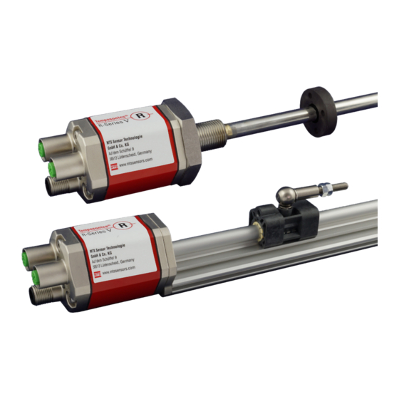
- Page 1 Temposonics ® Magnetostrictive Linear Position Sensors R-Series V EtherNet/IP™ Operation Manual...
-
Page 2: Table Of Contents
R-Series V EtherNet/IP™ Temposonics ® Operation Manual Table of contents 1. Introduction ..............................3 1.1 Purpose and use of this manual ................................3 1.2 Used symbols and warnings ..................................3 2. Safety instructions ............................. 3 2.1 Intended use ......................................3 2.2 Foreseeable misuse .................................... -
Page 3: Introduction
R-Series V EtherNet/IP™ Temposonics ® Operation Manual 1. Introduction 2.2 Foreseeable misuse Foreseeable misuse Consequence 1.1 Purpose and use of this manual The sensor will not work Wrong sensor connection properly or can be damaged Before starting the operation of Temposonics position sensors, ®... -
Page 4: Installation, Commissioning And Operation
R-Series V EtherNet/IP™ Temposonics ® Operation Manual 2.3 Installation, commissioning and operation 2.5 Warranty The position sensors must be used only in technically safe conditions. MTS Sensors grants a warranty period for the Temposonics ® To maintain this condition and to ensure safe operation, installation, position sensors and supplied accessories relating to material connection and service, work may be performed only by qualified defects and faults that occur despite correct use in accordance with... -
Page 5: Identification
R-Series V EtherNet/IP™ Temposonics ® Operation Manual 3. Identification R-Series V RP 3.1 Order code of Temposonics ® a Sensor model f Connection type 5 Profile 6 2 × M12 female connectors (5 pin), 1 × M8 male connector (4 pin) 8 2 ×... -
Page 6: Order Code Of Temposonics ® R-Series V Rh
R-Series V EtherNet/IP™ Temposonics ® Operation Manual R-Series V RH 3.2 Order code of Temposonics ® f Connection type a Sensor model 6 2 × M12 female connectors (5 pin), 5 Rod 1 × M8 male connector (4 pin) 8 2 × M12 female connectors (5 pin), b Design 1 ×... -
Page 7: Nameplate
R-Series V EtherNet/IP™ Temposonics ® Operation Manual 3.3 Nameplate Order code RH5SA0080U01D561U201 MAC: 00-03-CA-00-58-F6 MAC address S/N: 15030203 Serial number Date of Production 12JAN2018 Fig. 1: Example of nameplate of a R-Series V RH5 sensor with EtherNet/IP™ output 3.4 Approvals •... -
Page 8: Product Description And Commissioning
R-Series V EtherNet/IP™ Temposonics ® Operation Manual 4. Product description and commissioning 4.1 Functionality and system design Position magnet (Magnetic fi eld) Product designation Sensing element (Waveguide) R-Series V • Position sensor Temposonics ® Sensor model R-Series V RP (profile sensor) •... -
Page 9: Styles And Installation Of Temposonics ® R-Series V Rp
R-Series V EtherNet/IP™ Temposonics ® Operation Manual R-Series V RP 4.2 Styles and installation of Temposonics ® RP5-M (connection type D58) (0.2) Sensor electronics housing Null zone Stroke length Dead zone 48 (1.89) 28 (1.1) 25…6350 / 71* (0.67) (2.28) (1…250) (2.6 / 2.8*) e.g. -
Page 10: Styles And Installation Of Temposonics ® R-Series V Rh
R-Series V EtherNet/IP™ Temposonics ® Operation Manual R-Series V RH 4.3 Styles and installation of Temposonics ® RH5-M/S-A/-V – RH5 with threaded flange M18×1.5 or ¾"×16UNF (connection type D58) Sensor electronics housing Null zone Stroke length Dead zone 25…7620 63.5 / 66* (2.68) (2.01) (1…300) - Page 11 R-Series V EtherNet/IP™ Temposonics ® Operation Manual RH5-J-A/-V – RH5 with threaded flange M22×1.5 and Ø 12.7 mm rod (connection type D58) Sensor electronics housing Null zone Stroke length Dead zone 25…7620 73.6 (0.67) (2.68) (2.01) (1…300) (2.9) Port 1 L/A L/A Port 2 Threaded flange »J«: M22×1.5-6g (1.89)
- Page 12 R-Series V EtherNet/IP™ Temposonics ® Operation Manual Installation of RH5 with threaded flange In the case of threaded flange M18×1.5-6g or M22×1.5-6g, provide Fix the sensor rod via threaded flange M18×1.5-6g, M22×1.5-6g or a screw hole based on ISO 6149-1 (Fig. 11). See ISO 6149-1 for further ¾"-16 UNF-3A.
-
Page 13: Magnet Installation
R-Series V EtherNet/IP™ Temposonics ® Operation Manual Concentric mounting 4.4 Magnet installation of block magnet Magnet Typical sensors Benefits Rod model Ring magnets • Rotationally symmetrical Air gap: 3 ±2 (RH5) magnetic field 8 ±2 (0.12 ±0.08) (0.31 ±0.08) Sensor element Profile &... - Page 14 R-Series V EtherNet/IP™ Temposonics ® Operation Manual Start- and end positions of the position magnets Consider the start and end positions of the position magnets during the installation. To ensure that the entire stroke length is electrically usable, the position magnet must be mechanically mounted as follows. RP5 with U-magnet RH5 with ring magnet / U-magnet Sensor electronics housing...
- Page 15 R-Series V EtherNet/IP™ Temposonics ® Operation Manual Multi-position measurement The minimum distance between the magnets is 75 mm (3 in.). RP5 with U-magnet ≥ 75 (≥ 3) RP5 with magnet sliders ≥ 75 (≥ 3) RP5 with block magnets ≥ 75 (≥ 3) RH5 with ring magnets / U-magnets ≥...
-
Page 16: Replacement Of Sensor
R-Series V EtherNet/IP™ Temposonics ® Operation Manual 3. Insert the new base unit. 4.5 Replacement of sensor Mount the ground lug on a screw. Tighten the screws. The base unit of the sensor models RH (RH5-B) is replaceable as shown in Fig. 20 and Fig. 21. The sensor can be replaced without interrupting the hydraulic circuit. -
Page 17: Electrical Connections
R-Series V EtherNet/IP™ Temposonics ® Operation Manual 4.6 Electrical connections Connector wiring Connect the sensor directly to the control system, indicator or other Placement of installation and cabling have decisive influence on evaluating systems as follows: the sensor‘s electromagnetic compatibility (EMC). Hence correct installation of this active electronic system and the EMC of the entire Port 1 Port 2... - Page 18 R-Series V EtherNet/IP™ Temposonics ® Operation Manual Signal Port 1 – M12 female Function connector (D-coded) Tx (+) Rx (+) Tx (−) Rx (−) View on sensor Not connected Port 2 – M12 female Function connector (D-coded) Tx (+) Rx (+) Tx (−) Rx (−) View on sensor...
-
Page 19: Frequently Ordered Accessories
R-Series V EtherNet/IP™ Temposonics ® Operation Manual 4.7 Frequently ordered accessories – Additional options available in our Accessories Guide 551 444 Position magnets 15.2 57 (2.24) (1.65) (0.6) (1.69) (0.55) (1.69) (0.94) (0.55) 49 (1.93) (0.79) (0.79) (0.79) 40 (1.58) 40 (1.57) 40 (1.57) 40 (1.57) - Page 20 R-Series V EtherNet/IP™ Temposonics ® Operation Manual O-rings Mounting hardware ¾"-16 UNF-3A Ø 19.3 M18×1.5-6g (0.34) Ø 16.4 (0.43) (Ø 0.76) (Ø 0.65) Ø 2.2 Ø 2.2 (Ø 0.09) (Ø 0.09) O-ring for threaded fl ange O-ring for threaded fl ange Hex jam nut M18×1.5-6g Hex jam nut ¾"-16 UNF-3A ¾"-16 UNF-3A...
- Page 21 R-Series V EtherNet/IP™ Temposonics ® Operation Manual Cables PUR cable PVC cable Cable with M12 D-coded male Cable with M12 D-coded male Part no. 530 125 Part no. 530 108 connector (4 pin), straight – M12 connector (4 pin), straight – RJ45 D-coded, male connector (4 pin), male connector, straight straight...
-
Page 22: Operation
Port 1 L/A L/A Port 2 Green Information R-Series V EtherNet/IP™ Temposonics ® Connection established Operation Manual Flashing No connection Unrecoverable error Flashing Recoverable error 5. Operation Port 1 L/A (IN) 5.1 LED Status EtherNet/IP™ LED status Port 1 L/A L/A Port 2 Connection indicator Green... -
Page 23: Programming And Configuration
R-Series V EtherNet/IP™ Temposonics ® Operation Manual 6. Programming and configuration NOTICE 1. Choose an IP address that is not being used on your network or subnetwork. 6.1 IP address Configuration 2. After the IP address is assigned to the sensor, record the IP address and have it available as you will need it to communicate An example of configuring an MTS EtherNet/IP™... - Page 24 R-Series V EtherNet/IP™ Temposonics ® Operation Manual 6.2.5 Apply power to the sensor. The sensor should take around 10 to 6.2.9 Exit the BOOT/DHCP Server software. If installing the MTS 15 seconds to begin to broadcast its MAC ID. EtherNet/IP™ EDS file (download at www.mtssensors.com) 6.2.6 Verify that your IP address and MAC ID appear in the ‘Request continue with chapter 7.1.
-
Page 25: Integration In Rslogix 5000
R-Series V EtherNet/IP™ Temposonics ® Operation Manual 7. Integration in RSLogix 5000 7.1 Install the MTS EtherNet/IP™ EDS file 7.1.3 The ‘EDS Wizard’ window opens, click Next, in the ‘Options’ window select Register an EDS file(s) and click “Next”. The EDS file for the R-Series V EtherNet/IP™ sensor is available at www.mtssensors.com. - Page 26 R-Series V EtherNet/IP™ Temposonics ® Operation Manual 7.1.4 The ‘Registration’ window opens, click Browse and select the 7.1.6 The ‘Final Task Summary’ window opens, click “Next”. EDS file provided either with the sensor or downloaded from the MTS website. Click “Next”. Fig.
-
Page 27: Add Sensor To I/O Configuration Using Eds File
R-Series V EtherNet/IP™ Temposonics ® Operation Manual 7.2 Add sensor to I/O configuration using EDS file 7.2.2 In the Select Module Type window, choose “R-Series EtherNet/ IP” and click “Create”. 7.2.1 After completing the EDS wizard, return to the main window of RSLogix 5000. -
Page 28: Add Sensor To I/O Configuration Without Using Eds File
R-Series V EtherNet/IP™ Temposonics ® Operation Manual 7.2.4 Verify that the new sensor is listed in the I/O Configuration tree. 7.3 Add sensor to I/O configuration without using EDS file Before you begin, you will need the sensors static IP address you recorded in from step 6.2.7. -
Page 29: Set Module Rpi
R-Series V EtherNet/IP™ Temposonics ® Operation Manual 7.3.4 In the ‘New Module’ window (Fig. 44) perform step 7.3.4.1 – 7.4 Set Module RPI 7.3.4.4 to configure the new generic ethernet module to the R-Series EtherNet/IP™ sensor. 7.4.1 Click the “Connection” tab. Set the “Requested Packet Interval” (RPI) value and press “OK”. -
Page 30: Verify Generic Ethernet Module
R-Series V EtherNet/IP™ Temposonics ® Operation Manual 7.6 Verify Generic Ethernet Module 7.6.1 In the ‘I/O configuration tree’, click to open the ‘Controller Tags’ directory. The controller tag table displays in the left pane (Fig. 47). The description column fields will be blank by default. Fig. - Page 31 R-Series V EtherNet/IP™ Temposonics ® Operation Manual 7.6.3 Locate Data Byte [0] through [5] In the ‘Name’ column. In the ‘Description’ column, enter the following Data Byte field information. Name Description Values Description Data Byte [0] Data format 4 bytes signed position, 4 bytes signed velocity (repeats for each magnet) 4 bytes signed position (repeats for each magnet) 4 bytes signed velocity (repeats for each magnet) (default value)
-
Page 32: Controller Tags Input Data
R-Series V EtherNet/IP™ Temposonics ® Operation Manual 7.7 Controller tags input data The following illustrates an example of 'Controller Tags' information based on the factory default configuration: Fig. 48: Controller tags 'Controller Tags' information Examples based on the factory default configuration are as follows: 7.8.1 Run/Idle Header Data[0] is always the Run/Idle header. -
Page 33: Maintenance And Troubleshooting
R-Series V EtherNet/IP™ Temposonics ® Operation Manual 8. Maintenance and troubleshooting 8.1 Error conditions, troubleshooting 8.4 List of spare parts See chapter "5. Operation" on page 22. No spare parts are available for this sensor. 8.2 Maintenance 8.5 Transport and storage The sensor is maintenance-free. -
Page 34: Technical Data
R-Series V EtherNet/IP™ Temposonics ® Operation Manual 10. Technical data R-Series V RP 9.1 Technical data Temposonics ® Output Interface EtherNet/IP™ Data protocol Encoder CIP device profile with CIP Sync and DLR capabilities Data transmission rate 100 MBit/s (maximum) Measured value Position, velocity / option: Simultaneous multi-position and multi-velocity measurements up to 20 magnets Measurement parameters Resolution: Position... -
Page 35: Technical Data Temposonics ® R-Series V Rh
R-Series V EtherNet/IP™ Temposonics ® Operation Manual R-Series V RH 9.2 Technical data Temposonics ® Output Interface EtherNet/IP™ Data protocol Encoder CIP device profile with CIP Sync and DLR capabilities Data transmission rate 100 MBit/s (maximum) Measured value Position, velocity / option: Simultaneous multi-position and multi-velocity measurements up to 20 magnets Measurement parameters Resolution: Position 1…500 µm (selectable) -
Page 36: Appendix I
Equipment handling is safe. Personnel exposure to health risks during transport and repair is excluded. Stamp Signature Date GERMANY MTS Systems Corporation MTS Sensor Technologie Tel. + 49 - 23 51- 95 87 0 Tel. +1 919 677-0100 Sensors Division GmbH &... -
Page 37: Appendix Ii
R-Series V EtherNet/IP™ Temposonics ® Operation Manual 12. Appendix II C Y L I N D E R P O R T D E T A I L S P O R T D E TA I L ( P D ) F O R R H 5 - S : NOTES: 1. - Page 38 MTS, Temposonics and Level Plus are registered trademarks of MTS Systems Corporation in the United States; MTS SENSORS and the MTS SENSORS logo are trademarks of MTS Systems Corporation within the United States. These trademarks may be protected in other countries. All other trademarks are the property of their respective owners. Copyright © 2018 MTS Systems Corporation. No license of any intellectual property rights is granted.
Need help?
Do you have a question about the R Series V and is the answer not in the manual?
Questions and answers