
Related Manuals for MTS Systems Temposonics G Series


Summary of Contents for MTS Systems Temposonics G Series
- Page 1 Temposonics ® Magnetostrictive Linear Position Sensors Temposonics G-Series ® Brief Instructions...
-
Page 2: Table Of Contents
Temposonics G-Series ® Brief Instructions Table of contents 1. Introduction ..................................3 2. Safety instructions ................................4 2.1 Intended use ..................................4 2.2 Forseeable misuse .................................4 2.3 Installation, commissioning and operation ........................5 2.4 Safety instructions for use in explosion-hazardous areas ....................5 2.5 Warranty ..................................5 2.6 Return ....................................5 2.7 Maintenance &... -
Page 3: Introduction
Temposonics G-Series ® Brief Instructions 1. Introduction 1.1 Purpose and use of this manual Before starting the operation of Temposonics sensors ® read this documentation thoroughly and follow the safety information. Keep the manual for future reference! The content of this technical documentation is intended to provide information on mounting, installation and commis- sioning by qualified automation personnel or instructed... -
Page 4: Safety Instructions
Temposonics G-Series ® Brief Instructions 2. Safety instructions 2.1 Intended use Do not reprocess the sensor afterwards. The sensor might be damaged. This product may be used only for the applications defined under item 1 only in conjunction with the third-party devices and components recommended or approved by MTS Sensors. -
Page 5: Installation, Commissioning And Operation
Temposonics G-Series ® Brief Instructions 2.3 Installation, commissioning and operation 2.5 Warranty The position sensors must be used only in technically safe MTS Sensors grants a warranty period for the Temposonics ® condition. To maintain this condition and to ensure safe position sensors and supplied accessories relating to operation, installation, connection and service, work may material defects and faults that occur despite correct use in... -
Page 6: Identification
Temposonics G-Series ® Brief Instructions 3. Identification Nameplate (e.g. G-Series GP Analog) Approvals and certificates Stroke length (e.g. 850 mm) You will find approvals and certificates in the sensor specific operation manuals. Connection type Sensor model Part no. Output version GP-S-0850M-D60-1-V0 Output 0 - 10 V... -
Page 7: Temposonics ® G-Series Gt2 / Gt3
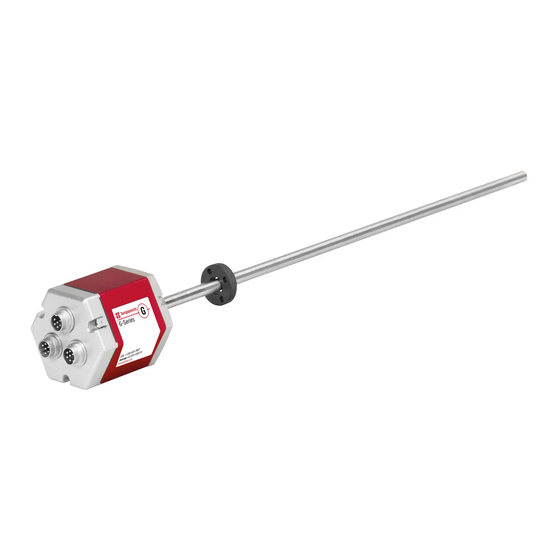
Temposonics G-Series ® Brief Instructions 3.3 Temposonics G-Series GT2 / GT3 (rod sensor with redundant electronics) ® Available output: Position magnet • Analog (U- or ring magnet) Sensor electronics housing Connector or Pressure-proof rod cable outlet with sensor element Threaded flange (M18×1.5-6g or ¾"-16 UNF-3A) Manuals &... -
Page 8: Installation & Mounting
Temposonics G-Series ® Brief Instructions 4. Installation & mounting 4.1 Magnet installation Centered mounting of block magnet Typical use of magnets For: GH & GT2 / GT3 • Rotationally symmetrical magnetic field Ring magnet Air gap: 3 ±2 8 ±2 For: GH, GT2 / GT3 &... -
Page 9: Mounting Dimensions Of G-Series
Temposonics G-Series ® Brief Instructions 4.2 Mounting dimensions of G-Series G-Series GP with U-magnet G-Series GP with magnet slider »S«, »N«, »V«, »G« Sensor electronics housing Sensor electronics housing Reference edge of mounting Reference edge of mounting Start position: 12 Start position Stroke length Stroke length... -
Page 10: Multi-Position Measurement Distances
Temposonics G-Series ® Brief Instructions 4.3 Multi-position measurement distances Multi-position measurement with G-Series GP / GH sensors and Start / Stop output is possible, with a simultaneous measuring up to 9 positions The stroke length influences the maximum number of magnets. Note the minimum distance between the magnets. G-Series GP with U-magnet G-Series GP with magnet slider »S«, »N«, »V«, »G«... -
Page 11: Electrical Connections
Temposonics G-Series ® Brief Instructions 5. Electrical connections Placement of installation and cabling have decisive influence Outputs on the sensor’s electromagnetic compatibility (EMC). Hence • Analog correct installation of this active electronic system and the • Start / Stop EMC of the entire system must be ensured by using suitable metal connectors, shielded cables and grounding. - Page 12 551515 Revision D (EN) 06/2016 GERMANY MTS, Temposonics and Level Plus are registered MTS Systems Corporation MTS Sensor Technologie trademarks of MTS Systems Corporation in the Sensors Division GmbH & Co. KG United States; MTS SENSORS and the MTS 3001 Sheldon Drive Auf dem Schüffel 9...
Need help?
Do you have a question about the Temposonics G Series and is the answer not in the manual?
Questions and answers