
Related Manuals for MTS Systems Temposonics R V Series


Summary of Contents for MTS Systems Temposonics R V Series
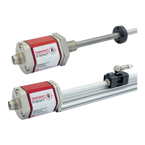
- Page 1 Temposonics ® Magnetostrictive Linear Position Sensors R-Series V Analog Temposonics ® Operation Manual...
-
Page 2: Table Of Contents
R-Series V Analog Temposonics ® Operation Manual Table of contents 1. Introduction ..............................3 1.1 Purpose and use of this manual ................................3 1.2 Used symbols and warnings ..................................3 2. Safety instructions ............................. 3 2.1 Intended use ......................................3 2.2 Foreseeable misuse .................................... -
Page 3: Introduction
R-Series V Analog Temposonics ® Operation Manual 1. Introduction 2.2 Foreseeable misuse Foreseeable misuse Consequence 1.1 Purpose and use of this manual The sensor will not work Wrong sensor connection properly or can be damaged Before starting the operation of Temposonics position sensors, ®... -
Page 4: Installation, Commissioning And Operation
R-Series V Analog Temposonics ® Operation Manual 2.3 Installation, commissioning and operation 2.5 Warranty The position sensors must be used only in technically safe conditions. MTS Sensors grants a warranty period for the Temposonics ® To maintain this condition and to ensure safe operation, installation, position sensors and supplied accessories relating to material connection and service, work may be performed only by qualified defects and faults that occur despite correct use in accordance with... -
Page 5: Identification
R-Series V Analog Temposonics ® Operation Manual 3. Identification 3.1 Order code of Temposonics ® optional a Sensor model f Connection type 0 M16 male connector (6 pin) 5 Profi le X XX m PUR cable (part no. 530 052) H01…H30 (1…30 m/3…99 ft.) b Design See “Frequently ordered accessories”... - Page 6 R-Series V Analog Temposonics ® Operation Manual l Max speed or velocity value (optional: use when “Function” is 2 or 3) For metric stroke lengths encode speed or velocity in m/s for the values 0.01 to 9.99 m/s (001…999) For US customary stroke lengths encode speed or velo- city in inches/s for the values 1 to 400 in./s (001…400) Use the codes (00E) for 0.025 m/s, and (A00) for 10.0 m/s to provide backwards compatibility for these predecessor model of the R-Series.
-
Page 7: Order Code Of Temposonics ® Rh5
R-Series V Analog Temposonics ® Operation Manual 3.2 Order code of Temposonics ® optional a Sensor model f Connection type 5 Rod 0 M16 male connector (6 pin) X XX m PUR cable (part no. 530 052) H01…H30 (1…30 m/3…99 ft.) b Design See “Frequently ordered accessories”... - Page 8 R-Series V Analog Temposonics ® Operation Manual l Max speed or velocity value (optional: use when “Function” is 2 or 3) For metric stroke lengths encode speed or velocity in m/s for the values 0.01 to 9.99 m/s (001…999) For US customary stroke lengths encode speed or velo- city in inches/s for the values 1 to 400 in./s (001…400) Use the codes (00E) for 0.025 m/s, and (A00) for 10.0 m/s to provide backwards compatibility for these predecessor model of the R-Series.
-
Page 9: Nameplate
R-Series V Analog Temposonics ® Operation Manual 3.3 Nameplate Order code RH5MA0250M01D601A100 Analog output 4…20 mA Serial number Date of Production 01MAR2020 S/N: 12345678 Fig. 1: Example of nameplate of a R-Series V RH5 sensor with Analog output 3.4 Approvals •... -
Page 10: Product Description And Commissioning
R-Series V Analog Temposonics ® Operation Manual 4. Product description and commissioning 4.1 Functionality and system design Position magnet (Magnetic fi eld) Product designation Sensing element (Waveguide) R-Series V • Position sensor Temposonics ® Sensor model R-Series V RP5 (profile sensor) •... -
Page 11: Styles And Installation Of Temposonics ® Rp5
R-Series V Analog Temposonics ® Operation Manual 4.2 Styles and installation of Temposonics ® RP5-M-A/-V, example: Connection type D60 (connector output) Sensor electronics housing Null zone Stroke length Dead zone 48 (1.89) 11.7 25…6350 66/71* (0.46) (2.28) (1.1) (1…250) (2.6/2.8*) e.g. -
Page 12: Styles And Installation Of Temposonics ® Rh5
R-Series V Analog Temposonics ® Operation Manual 4.3 Styles and installation of Temposonics ® RH5-M/S-A/-V – RH5 with threaded fl ange M18×1.5-6g or ¾"-16 UNF-3A, example: Connection type D60 (connector output) Sensor electronics housing Null zone Stroke length Dead zone 11.7 25…7620 63.5/66*... - Page 13 R-Series V Analog Temposonics ® Operation Manual RH5-J-A/-V – RH5 with threaded fl ange M22×1.5-6g and Ø 12.7 mm rod, example: Connection type D60 (connector output) Sensor electronics housing Null zone Stroke length Dead zone 11.7 25…5900 73.6 (0.46) (2.68) (2.01) (1…232) (2.9)
- Page 14 R-Series V Analog Temposonics ® Operation Manual Installation of RH5 with threaded flange In the case of threaded flange M18×1.5-6g or M22×1.5-6g, provide Fix the sensor rod via threaded flange M18×1.5-6g, M22×1.5-6g or a screw hole based on ISO 6149-1 (Fig. 11). See ISO 6149-1 for further ¾"-16 UNF-3A.
-
Page 15: Magnet Installation
R-Series V Analog Temposonics ® Operation Manual Centered mounting 4.4 Magnet installation of block magnet Typical use of magnets Magnet Typical sensors Benefi ts Air gap: 3 ±2 8 ±2 (0.12 ±0.08) Ring magnets Rod model • Rotationally symmetrical (0.31 ±0.08) Sensor element (RH5) magnetic fi eld... - Page 16 R-Series V Analog Temposonics ® Operation Manual NOTICE Start- and end positions of the position magnets Consider the start and end positions of the position magnets during On all sensors, the areas left and right of the active stroke length are the installation.
-
Page 17: Replacement Of Base Unit
R-Series V Analog Temposonics ® Operation Manual 3. Insert the new base unit. 4.5 Replacement of base unit Install the ground lug on a screw. Tighten the screws. The base unit of the sensor model RH5 (RH5-B) is replaceable as shown in Fig. -
Page 18: Electrical Connections
R-Series V Analog Temposonics ® Operation Manual NOTICE 4.6 Electrical connections 1. In addition to the functions listed for the output 2 wiring Placement of installation and cabling have decisive influence on connections, pins 3 and 4 (or the yellow and green wires) can the sensor‘s electromagnetic compatibility (EMC). -
Page 19: Frequently Ordered Accessories For Rp5 Design
R-Series V Analog Temposonics ® Operation Manual 4.7 Frequently ordered accessories for RP5 design – Additional options available in our Accessories Guide 551 444 Position magnets 15.2 57 (2.24) (0.6) (1.65) (1.69) (0.94) (1.69) (0.55) (0.55) 49 (1.93) (0.79) (0.79) (0.79) 40 (1.57) 40 (1.57) -
Page 20: Frequently Ordered Accessories For Rh5 Design
R-Series V Analog Temposonics ® Operation Manual 4.8 Frequently ordered accessories for RH5 design – Additional options available in our Accessories Guide 551 444 Position magnets Ø 32.8 (Ø 1.29) Ø 4.3 Ø 32.8 Ø 30.5 Ø 25.4 (Ø 0.17) (Ø... -
Page 21: Frequently Ordered Accessories For Analog Output
R-Series V Analog Temposonics ® Operation Manual 4.9 Frequently ordered accessories for Analog output – Additional options available in our Accessories Guide 551 444 Cable connectors* Programming tools (2.13) 60.5 (2.38) 19.5 (0.77) M16 female connector (6 pin), straight M16 female connector (6 pin), angled TempoLink kit for Temposonics Hand programmer for analog output ®... -
Page 22: Programming
R-Series V Analog Temposonics ® Operation Manual 5. Programming 5.2 Introduction R-Series V Analog sensors are pre-configured at the Temposonics ® 5.1 Analog Output Options factory by the model number ordering code. For many applications, normal sensor installation and operation does not require additional R-Series V analog sensors can be ordered for single channel or dual adjustment. -
Page 23: Led Status
R-Series V Analog Temposonics ® Operation Manual Error 5.3 LED Status Description Troubleshooting Condition Configuration Invalid configuration of Check the configuration of The LED on the sensor displays the current sensor status. In normal Error the sensor the sensor. function the LED is continuously green. In other cases the color of the Contact MTS Sensors. -
Page 24: Programming Via Mts Sensors Service Tools
R-Series V Analog Temposonics ® Operation Manual NOTICE 5.4 Programming via MTS Sensors service tools In normal function the green LED on sensor is glowing permanently. Temposonics sensors can be easily adapted – without opening ® sensor housing – to changing measuring tasks via connecting wires. Therefore the user can use several MTS Sensors service tools which can be chosen from the accessories. - Page 25 R-Series V Analog Temposonics ® Operation Manual 5.4.2 Programming via cabinet programmer for analog output Analog input module Cabinet programmer for analog output (part no. 253 408), connected between sensor and control unit is provided for setup of measuring range by moving the magnet on desired Null/Span positions (minimum distance between setpoints: 25 mm) and pushing the Program /Run 24 VDC...
-
Page 26: Programming And Configuration
R-Series V Analog Temposonics ® Operation Manual 5.5 Programming and configuration 5.5.1 Connection of TempoLink smart assistant to sensor and power supply OU TP IN PU R-Series V Analog sensors can easily be adapted to changing SE NS 24 V measurement tasks via TempoLink smart assistant. - Page 27 R-Series V Analog Temposonics ® Operation Manual Connecting a computer via USB connection 5.5.3 Establishing a connection via browser The TempoLink smart assistant can also be connected via USB. If the computer is Wi-Fi enabled deactivate Wi-Fi on the computer before After the connection via Wi-Fi or USB is established, open the browser setting up the USB connection.
- Page 28 R-Series V Analog Temposonics ® Operation Manual 5.5.4 Adjusting Sensor Settings Using the TempoLink Smart 2. To adjust the sensor settings click “Enter Command Mode” on Assistant the Interface page, type “COMMAND” into the text field, and then click “OK”. 1.
- Page 29 R-Series V Analog Temposonics ® Operation Manual 3. After entry into command mode, the connection icon in the top 4. The sensor shown in this example has been configured in the right will change from green to blue, and the sensor settings can factory for an output range of 4…20 mA.
- Page 30 R-Series V Analog Temposonics ® Operation Manual 5. The next setting is for output at set point one (start of stroke). 6. The next setting is for output at set point two (end of stroke). For this example, the new value is 0.1 mA, as shown in the drop- The new value entered in the drop-down box is 19.9 mA.
- Page 31 R-Series V Analog Temposonics ® Operation Manual 7. The last setting for channel one output is for the error output 8. The factory setting for channel one function is magnet 1 position. value. For this example, the factory default value of 20.7 mA For most all applications this setting is not typically changed.
- Page 32 R-Series V Analog Temposonics ® Operation Manual 9. The channel one over range setting allows the position output 10. The set point units setting can be used to change between values to continue to increase or decrease when the magnet millimeters and inches.
-
Page 33: Maintenance And Troubleshooting
R-Series V Analog Temposonics ® Operation Manual 6. Maintenance and troubleshooting 11. After the parameters have been configured, click the button EXIT COMMAND MODE. The “Exit Command Mode” window for exiting the command mode will open. Click the button SAVE AND EXIT to 6.1 Error conditions, troubleshooting exit the command mode and to transfer the changed parameters to the sensor (Fig. -
Page 34: Technical Data
R-Series V Analog Temposonics ® Operation Manual 8. Technical data 8.1 Technical data Temposonics ® Output Analog Voltage: 0…10 /10…0/−10…+10/+10…−10 VDC (min. controller load > 5 kΩ) Current: 4(0)…20/20…4(0) mA (min./max. load 0/500 Ω) Measured output variables Position for one or two position magnets Position + speed (without direction) or velocity (with direction) for one position magnet Position for one position magnet + temperature inside the sensor electronics housing Measurement parameters... -
Page 35: Technical Data Temposonics ® Rh5
R-Series V Analog Temposonics ® Operation Manual 8.2 Technical data Temposonics ® Output Analog Voltage: 0…10 /10…0/−10…+10/+10…−10 VDC (min. controller load > 5 kΩ) Current: 4(0)…20/20…4(0) mA (min./max. load 0/500 Ω) Measured output variables Position for one or two position magnets Position + speed (without direction) or velocity (with direction) for one position magnet Position for one position magnet + temperature inside the sensor electronics housing Measurement parameters... - Page 36 Signature Signature Date Date GERMANY GERMANY MTS Systems Corporation MTS Systems Corporation MTS Sensor Technologie MTS Sensor Technologie Tel. + 49 - 23 51- 95 87 0 Tel. + 49 - 23 51- 95 87 0 Tel. +1 919 677-0100 Tel.
- Page 37 R-Series V Analog Temposonics ® Operation Manual 10. Appendix II C Y L I N D E R P O R T D E T A I L S P O R T D E TA I L ( P D ) F O R R H 5 - S : NOTES: 1.
-
Page 38: Glossary
R-Series V Analog Temposonics ® Operation Manual 11. Glossary Analog output For a sensor with analog output, the measured value is output as an analog voltage signal or current signal. Differential For differential measurement, the distance between the two position magnets is output as a value. - Page 39 MTS, Temposonics and Level Plus are registered trademarks of MTS Systems Corporation in the United States; MTS SENSORS and the MTS SENSORS logo are trademarks of MTS Systems Corporation within the United States. These trademarks may be protected in other countries. All other trademarks are the property of their respective owners. Copyright © 2020 MTS Systems Corporation. No license of any intellectual property rights is granted.
Need help?
Do you have a question about the Temposonics R V Series and is the answer not in the manual?
Questions and answers