Table of Contents
Advertisement
Quick Links
Solenoid valve
VZWF-...-M22C
Operating instructions
Original: de
Solenoid valve VZWF-...-M22C
. . . . . . . . . . . . . . . . . . . . . . . . . . . . . . . . . . .
1
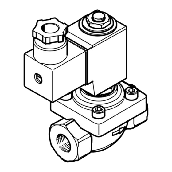
Design
4
3
2
1
1
Port 1: Input
2
Valve body
3
Electrical plug with seal and
mounting screw
4
Solenoid coil mounting with
shaped rubber part, washer and
1)
hex nut
5
Solenoid coil mounting with
O-ring, aluminium shaped part,
toothed disc and socket head
1)
screw
1) Mounting variant dependent on the size
Fig. 1
2
Function
The solenoid valve VZWF–...–M22C is a forced 2/2-way valve
with solenoid coil.
The membrane of the valve is coupled with the magnetic core
of the coil. This allows the forced solenoid valve to switch
between input and output without pressure difference.
The solenoid valve VZWF–...–M22C is closed in the de-ener
gised state (Normally Closed - NC).
When current flows, the armature opens the pilot control hole in the valve seat
seal and lifts the membrane from the valve seal either directly or supported by
differential pressure of the medium pressure. If the power supply is cut off, the
pilot control hole is closed by spring force. The supply pressure affects the mem
brane and supports the sealing of the membrane on the valve seat.
Festo AG & Co. KG
Postfach
73726 Esslingen
Deutschland
+49 711 347-0
www.festo.com
8065862
1611b
[8065864]
English
6
Solenoid coil
7
O-ring
8
Armature guiding tube
9
Port 2: Output
aJ
Arrow for flow direction
aA
Thread for mounting bracket
Fig. 2
3
Application
Solenoid valves of the VZWF–...–M22C series are intended to be used for con
trolling the flow of gaseous and liquid media in rigid piping systems.
The valve is suitable for vacuum operation with p
• The product may only be used in its original state without unauthorized modific
ations. Opening the valve body or dismantling the armature guiding tube is not
permitted.
• Take into consideration the operating conditions at the location of use. Provide
sufficient thermal circulation.
• Use the product only in perfect technical condition.
• Only use media in accordance with specification. Before using other media,
please contact our customer support.
• Operation with chemically unstable gases, abrasive media and hard materials is
not permitted.
• Use the solenoid valves only in the flow direction indicated.
• Wear suitable personal protective clothing, e.g. safety shoes and safety gloves.
• Comply with all applicable national and international regulations.
• Dispose of the product in an environmentally friendly manner. When doing this,
also take residual media into account (potential recycling of hazardous waste).
Return to Festo
Hazardous substances can endanger the health and safety of personnel and cause
damage to the environment. To prevent hazards, the product should only be re
turned upon explicit request by Festo.
– Consult your regional Festo contact.
– Complete the declaration of contamination and attach it to the outside of the
packaging.
– Comply with all of the legal requirements for the handling of hazardous sub
stances and the transport of dangerous goods.
4
Product variants
5
Characteristic
Type
Version
Valve type
Valve function
6
Connection to valves
and fittings
7
Nominal diameter
Sealing materials
8
Nominal operating
voltage
9
Electrical connection
Medium pressure
aJ
Corrosion protection
aA
Fig. 3
5
Transport and storage
• When shipping used products: Comply with all legal requirements for handling
hazardous substances and transporting dangerous goods.
For return to Festo è Kapitel 3.
• Store the product in a cool, dry, UV- and corrosion-protected environment.
6
Installation
Note
Installation should only be conducted by qualified specialized personnel.
Avoid mechanical stresses, particularly on the solenoid coil and the armature
guiding tube.
Requirements
– The piping system is unpressurized, and no medium flows in it.
– The lines are clean.
– The lines ends are mounted.
– The power supply is switched off.
Note
For fault-free operation, the effective line cross section at the input end should
be at least as large as it is at the output end. Take proper account of the pipeline
cross sections, line lengths and elements that may reduce the flow rate (angle
sections etc.).
Clean valve
Residues of grease may be evident on the product due to the production process
used.
• Clean valve immediately before installation.
> 100 mbar.
abs
Value
Description
VZWF
Solenoid valve, forced
–, B
Standard, Function-optimised
L
In-line valve
M22C
2/2-way valve, normally closed (NC)
G14 bis G2
Pipe thread in accordance with DIN ISO 228
N14 bis N2
NPT standard pipe thread in accordance with
ANSI B 1.20.1
135, 275, 400, 500
13,5 mm, 27,5 mm, 40 mm, 50 mm
–, E, V
Standard (NBR), EPDM, FPM
1, 2A, 3A
24 V DC, 110 V AC (50-60 Hz), 230 V AC (50-60 Hz)
P4
Plug socket, 3-pin
6, 10
max. 6 bar, max. 10 bar
–, R1
Standard (brass), Stainless steel
Advertisement
Table of Contents

Related Manuals for Festo VZWF-...-M22C series


Summary of Contents for Festo VZWF-...-M22C series
- Page 1 • When shipping used products: Comply with all legal requirements for handling Valve body O-ring hazardous substances and transporting dangerous goods. For return to Festo è Kapitel 3. Electrical plug with seal and Armature guiding tube mounting screw Port 2: Output •...
- Page 2 Connect lines Troubleshooting 1. Bring the solenoid valve into its installation position. Please note the direction of Malfunction Possible cause Remedy flow. The permissible flow direction is marked by an arrow on the valve body. In Solenoid valve Solenoid valve faulty. •...
Need help?
Do you have a question about the VZWF-...-M22C series and is the answer not in the manual?
Questions and answers