
Related Manuals for Feig Electronic OBID i-scan ID ISC.M02


Summary of Contents for Feig Electronic OBID i-scan ID ISC.M02
- Page 1 MONTAGE ® OBID i-scan INSTALLATION ID ISC.M02 (deutsch / english) final public (B) 2003-02-11 M20301-0de-ID-B.doc...
- Page 2 ® OBID i-scan Montage ID ISC.M02 FEIG ELECTRONIC GmbH Seite 2 von 42 M20301-0de-ID-B.doc...
- Page 3 ® OBID i-scan Montage ID ISC.M02 deutsche Version ab Seite 4 english version from page 24 FEIG ELECTRONIC GmbH Seite 3 von 42 M20301-0de-ID-B.doc...
- Page 4 Hinweise jederzeit dankbar. Die in diesem Dokument gemachten Installationsempfehlungen gehen von günstigsten Rahmenbedingun- gen aus. FEIG ELECTRONIC GmbH übernimmt keine Gewähr für die einwandfreie Funktion in systemfrem- den Umgebungen. FEIG ELECTRONIC GmbH übernimmt keine Gewährleistung dafür, dass die in diesem Dokument enthal- tenden Informationen frei von fremden Schutzrechten sind.
-
Page 5: Table Of Contents
3.5. Montagehinweise......................19 3.5.1. Metallische Umgebung....................19 3.5.2. EMV-Beeinflussung über Zuleitungen ............... 19 3.5.3. EMV-Beeinflussung über magnetische Felder............20 4. Funkzulassungen 4.1. Europa (CE)........................21 4.2. USA (FCC) ........................21 5. Technische Daten FEIG ELECTRONIC GmbH Seite 5 von 42 M20301-0de-ID-B.doc... -
Page 6: Sicherheits- Und Warnhinweise - Vor Inbetriebnahme Unbedingt Lesen
Alle Arbeiten am Gerät und dessen Aufstellung müssen in Übereinstimmung mit den nationa- len elektrischen Bestimmungen und den örtlichen Vorschriften durchgeführt werden. Beim Arbeiten an dem Gerät müssen die jeweils gültigen Sicherheitsvorschriften beachtet • werden. FEIG ELECTRONIC GmbH Seite 6 von 42 M20301-0de-ID-B.doc... -
Page 7: Leistungsmerkmale Des Readermoduls Id Isc.m02
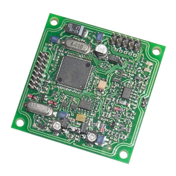
Readermodul mit integrierter Antenne, RS232-C- und Daten-/Takt- Schnittstelle, für eine Versorgungsspannung von 5 V DC 2.3. Lieferumfang Folgende Komponenten sind im Lieferumfang enthalten: Modultyp Lieferumfang ID ISC.M02-B 1 x Readermodul ID ISC.M02-B FEIG ELECTRONIC GmbH Seite 7 von 42 M20301-0de-ID-B.doc... -
Page 8: Montage Und Anschluss
® OBID i-scan Montage ID ISC.M02 3. Montage und Anschluss 3.1. Abmessungen Bild 3.1-1 zeigt die Maßzeichnung des Readermoduls ID ISC.M02. 50,0 44,0 Bild 3.1-1: Maßzeichnung des Readermoduls ID ISC.M02 FEIG ELECTRONIC GmbH Seite 8 von 42 M20301-0de-ID-B.doc... -
Page 9: Anschluss
+ 5 V DC * GND ** Nicht angeschlossen Nur geregelte DC-Spannungen verwenden ! Die GND-Pins 4 und 9 sind auf dem Readermodul direkt miteinander verbunden Tabelle 3.2-1: Belegung der Anschlussstiftleiste X1 FEIG ELECTRONIC GmbH Seite 9 von 42 M20301-0de-ID-B.doc... -
Page 10: Spannungsversorgung
Tabelle 3.2.1-1: Pinbelegung der Spannungsversorgung an X1 HINWEIS: • Eine Verpolung der Versorgungsspannung kann zur Zerstörung des Gerätes führen. • Versorgungsspannungen außerhalb der Spezifikation können zur Zerstörung des Gerä- tes führen. FEIG ELECTRONIC GmbH Seite 10 von 42 M20301-0de-ID-B.doc... -
Page 11: Rs232-Schnittstelle
Die Übertragungsparameter der Schnittstelle können per Softwareprotokoll konfiguriert werden. Tabelle 3.2.2-2 zeigt die Standardparameter der RS232-Schnittstelle. Parameter Standardeinstellung Baudrate 38400 Anzahl der Datenbits Parität Even Anzahl der Stoppbits Tabelle 3.2.2-2: Standardparameter der RS232-Schnittstelle. FEIG ELECTRONIC GmbH Seite 11 von 42 M20301-0de-ID-B.doc... -
Page 12: Daten-/Taktschnittstelle
4, 9 GND * Die GND-Pins 4 und 9 sind auf dem Readermodul direkt miteinander verbunden Tabelle 3.2.3-1: Pinbelegung der RS232-Schnittstelle an X1 Data Clock Host ID ISC.M02 Bild 3.2.3-1: Anschluss der Daten-/Taktschnittstelle FEIG ELECTRONIC GmbH Seite 12 von 42 M20301-0de-ID-B.doc... -
Page 13: Optionales Security-Modul Id Sam.m02
Bei Bedarf kann optional auf die Stiftleisten X3 und X4 ein Security-Modul vom Typ ID SAM.M02 aufgesteckt werden. Das Security-Modul ID SAM.M02 bietet zusätzliche Sicherheit durch kryptographische Datenüber- tragung zwischen Reader und Transponder. 25,0 Bild 3.2.4-1: Maßzeichnung ID ISC.M02 mit ID SAM.M02 FEIG ELECTRONIC GmbH Seite 13 von 42 M20301-0de-ID-B.doc... -
Page 14: Anzeigeelemente
• Blinkt kontinuierich mit einer Frequenz von 2 Hz. • Blinkt nach einem Reset vier mal. • Leuchtet nach einer erfolgreichen Kommunikation mit einem Transponder für 1 Sekunde. Tabelle 3.3-1: Standardeinstellung der LED´s FEIG ELECTRONIC GmbH Seite 14 von 42 M20301-0de-ID-B.doc... -
Page 15: Bedienelemente
Aktivierung des Hardware-Bootloaders : Nach einem Reset startet die CPU des Readers 2 - 3 seinen Hardware Bootloader und kann über diesen neu programmiert werden. Tabelle 3.4.1-1: Jumper J1 Standard- einstellung Bild 3.4.1-1: Jumper J1 FEIG ELECTRONIC GmbH Seite 15 von 42 M20301-0de-ID-B.doc... -
Page 16: Interne/Externe Antenne: Stiftleiste X2, Jumper J2 Und J3
• Werden die beiden Jumper J2 und J3 nach dem Anschluss einer externen Antenne nicht geöffnet, so wird der Sender des Readers durch beide Antennen belastet. Dies kann zu dessen Zerstörung führen! FEIG ELECTRONIC GmbH Seite 16 von 42 M20301-0de-ID-B.doc... -
Page 17: Nachgleich Der Internen Antenne: Trimmkondensator C65
Für den Abgleich der internen Antenne muss nun die Signalamplitude des 13,56 MHz-Signals mit Hilfe des Trimmkondensators C65 auf Maximum abgeglichen werden. Mit C65 Signalamplitude auf Maximum drehen ID ISC.M02 V1 V2 Bild 3.4.3-2: Messaufbau zum Abgleich der internen Antenne FEIG ELECTRONIC GmbH Seite 17 von 42 M20301-0de-ID-B.doc... - Page 18 • Trotz der hier beschriebenen Möglichkeit des Antennennachgleichs sollte der Abstand zwischen Reader und den umgebenden Metallflächen mindestens 3 cm betragen. Dabei sollte bedacht werden, dass sich auch andere Leiterplatten, je nach Kupferauflage, wie Metallflächen verhalten. FEIG ELECTRONIC GmbH Seite 18 von 42 M20301-0de-ID-B.doc...
-
Page 19: Montagehinweise
Trotz der internen EMV-Filter des Readers kann es durch starke Störungen auf der Spannungs- versorgung zu Beeinträchtigungen der Kommunikation zwischen Reader und Transponder kom- men. Beim Einbau eines ID ISC.M02 in ein anderes Gerät sollte daher auf eine möglichst saubere, stör- freie Spannungsversorgung geachtet werden. FEIG ELECTRONIC GmbH Seite 19 von 42 M20301-0de-ID-B.doc... -
Page 20: Emv-Beeinflussung Über Magnetische Felder
Bei der Festlegung der Position von Reader und Antenne in einem Gerät sollte dieses auf eventu- elle Störquellen in der oben angegebenen Form untersucht werden. Notfalls sind Abschirmmaß- nahmen zur Unterdrückung einer solchen Störquelle anzuwenden. FEIG ELECTRONIC GmbH Seite 20 von 42 M20301-0de-ID-B.doc... -
Page 21: Funkzulassungen
At the time of this printing, the antennas listed below were the only antennas approved for use with the ID ISC.M02 module. Use of other antennas must be approved by FEIG ELECTRONIC GmbH. Antennas approved: ID ISC.ANT100100; ID ISC.ANT4030 FEIG ELECTRONIC GmbH Seite 21 von 42 M20301-0de-ID-B.doc... -
Page 22: Technische Daten
– Betrieb -40°C bis +85°C – Lagerung Angewendete Normen • Zulassung Funk EN 300 330 – Europa FCC 47 CFR Part 15 – USA • EMV EN 301 489 • Sicherheit EN 60950 FEIG ELECTRONIC GmbH Seite 22 von 42 M20301-0de-ID-B.doc... - Page 23 ® OBID i-scan Montage ID ISC.M02 FEIG ELECTRONIC GmbH Seite 23 von 42 M20301-0de-ID-B.doc...
- Page 24 ELECTRONIC GmbH does not give any guarantee promise for perfect function in cross environments. FEIG ELECTRONIC GmbH assumes no responsibility for the use of any information contained in this manual and makes no representation that they free of patent infringement. FEIG ELECTRONIC GmbH does not convey any license under its patent rights nor the rights of others.
- Page 25 8.5.1. Metallic surroundings ....................39 8.5.2. EMC effects on cables ....................39 8.5.3. EMC effects from magnetic fields................40 9. Radio Approvals 9.1. Europe (CE)........................41 9.2. USA (FCC) ........................41 10. Technical Data FEIG ELECTRONIC GmbH Page 25 of 42 M20301-0de-ID-B.doc...
- Page 26 Works at the device and its installation have to be executed according to the national legal requirements and local prescriptions. When working on devices the valid safety regulations must be observed. • FEIG ELECTRONIC GmbH Page 26 of 42 M20301-0de-ID-B.doc...
-
Page 27: Performance Characteristics Of The Id Isc.m02 Reader Module
Reader Module with integrated antenna, RS232-C and data/clock in- terface, for a supply voltage of 5 V DC 7.3. Scope of delivery The following components are included: Module type Included ID ISC.M02-B 1 x Reader Module ID ISC.M02-B FEIG ELECTRONIC GmbH Page 27 of 42 M20301-0de-ID-B.doc... -
Page 28: Installation And Wiring
OBID Installation ID ISC.M02 8. Installation and wiring 8.1. Dimensions Fig. 3.1-1 shows the dimensions of the ID ISC.M02 Reader Module 50,0 44,0 Fig. 3.1-1: Dimensions of the ID ISC.M02 Reader Module FEIG ELECTRONIC GmbH Page 28 of 42 M20301-0de-ID-B.doc... -
Page 29: Wiring
Use only regulated DC power supplies ! GND-Pins 4 and 9 are to be connected directly to each other on the Reader Module Table 3.2-1: Pin assignments for Terminal X1 FEIG ELECTRONIC GmbH Page 29 of 42 M20301-0de-ID-B.doc... -
Page 30: Supply Voltage
Reader Module Table 3.2.1-1: Pin assignments for X1 NOTE: • Reversing the polarity of the supply voltage may destroy the device. • Supply voltages outside the specifications may destroy the device. FEIG ELECTRONIC GmbH Page 30 of 42 M20301-0de-ID-B.doc... -
Page 31: Rs232 Interface
The transmission parameters for the interface can be software-configured. Table 3.2.2-2 shows the standard parameters for the RS232 interface. Parameter Standard setting Baud rate 38400 No. of data bits Parity Even No. of stop bits Table 3.2.2-2: Standard parameters of the RS232 interface. FEIG ELECTRONIC GmbH Page 31 of 42 M20301-0de-ID-B.doc... -
Page 32: Data/Clock Interface
GND-Pins 4 and 9 are to be connected directly to each other on the Reader Module Table 3.2.3-1: Pin configuration for the RS232 interface on Terminal X1 Data Clock Host ID ISC.M02 Fig. 3.2.3-1: Connecting the data/clock-interface FEIG ELECTRONIC GmbH Page 32 of 42 M20301-0de-ID-B.doc... -
Page 33: Optional Security Module Id Sam.m02
If needed, the optional ID SAM.M02 Security Module can be connected to terminals X3 and X4. The ID SAM.M02 Security Module provided additional security by using cryptographic data trans- mission between the reader and transponder. 25,0 Fig. 3.2.4-1: Dimensions of ID ISC.M02 with ID SAM.M02 FEIG ELECTRONIC GmbH Page 33 of 42 M20301-0de-ID-B.doc... -
Page 34: Display Elements
• Flashes continuously at a frequency of 2 Hz. • Flashes 4x after a reset. • Comes on for 1 second after successful communication with a transponder. Table 3.3-1: Standard setting for the LEDs FEIG ELECTRONIC GmbH Page 34 of 42 M20301-0de-ID-B.doc... -
Page 35: Operating Elements
After a reset the reader’s CPU starts its hardware 2 - 3 bootloader, which can then be used for new pro- gramming. Table 3.4.1-1: Jumper J1 Bild 3.4.1-1: Jumper J1 Standard- setting FEIG ELECTRONIC GmbH Page 35 of 42 M20301-0de-ID-B.doc... -
Page 36: Internal/External Antenna: Terminal X2, Jumpers J2 And J3
• If both jumpers J2 and J3 are not removed after connecting an external antenna, the reader’s transmitter will be loaded by both antennas. This could result in permanent damage to the transmitter! FEIG ELECTRONIC GmbH Page 36 of 42 M20301-0de-ID-B.doc... -
Page 37: Retuning The Internal Antenna: Trim Capacitor C65
To tune the internal antenna, now set the signal amplitude of the 13.56 MHz signal to maximum using trim capacitor C65. Turn C65 to set amplitude to maximum ID ISC.M02 Bild 3.4.3-2: Configuration for tuning the internal antenna FEIG ELECTRONIC GmbH Page 37 of 42 M20301-0de-ID-B.doc... - Page 38 3 cm. Note that even other circuit boards may act like metal objects depending on how much copper they contain. FEIG ELECTRONIC GmbH Page 38 of 42 M20301-0de-ID-B.doc...
-
Page 39: Installation Notes
In spite of the internal EMC filters inside the reader, high levels of noise on the supply voltage can result in impairment of the communication between the reader and transponder. When installing an ID ISC.M02 into another device, be sure therefore that a clean, noise-free power supply is used. FEIG ELECTRONIC GmbH Page 39 of 42 M20301-0de-ID-B.doc... -
Page 40: Emc Effects From Magnetic Fields
When determining the position of the reader and antenna within a device, check the device for any possible sources of interference as described above. If necessary, use shielding to suppress such interference. FEIG ELECTRONIC GmbH Page 40 of 42 M20301-0de-ID-B.doc... -
Page 41: Radio Approvals
At the time of this printing, the antennas listed below were the only antennas approved for use with the ID ISC.M02 module. Use of other antennas must be approved by FEIG ELECTRONIC GmbH. Antennas approved: ID ISC.ANT100100; ID ISC.ANT4030 FEIG ELECTRONIC GmbH Page 41 of 42 M20301-0de-ID-B.doc... -
Page 42: Technical Data
– Operating -40°C to +85°C – Storage Applicable Norms • Radio Approval EN 300 330 – Europe FCC 47 CFR Part 15 – USA • EMC EN 301 489 • Safety EN 60950 FEIG ELECTRONIC GmbH Page 42 of 42 M20301-0de-ID-B.doc...
Need help?
Do you have a question about the OBID i-scan ID ISC.M02 and is the answer not in the manual?
Questions and answers