
Subscribe to Our Youtube Channel
Related Manuals for Feig Electronic ID ISC.M02.M8


Summary of Contents for Feig Electronic ID ISC.M02.M8
- Page 1 INSTALLATION MANUAL ID ISC.M02.M8 final – public (B) _02.doc 2020-06-03 – M02M8-IM-e...
- Page 2 FEIG ELECTRONIC call explicit attention that devices which are subject of this document are not designed with components and testing methods for a level of reliability suitable for use in or in connection with surgical implants or as critical components in any life support systems whose failure to perform can reasonably be expected to cause significant injury to a human.
-
Page 3: Table Of Contents
Installation ID ISC.M02.M8 Content ID ISC.M02.M8 Safety Instructions / Warning - Read before start-up ! Performance Characteristics of the ID ISC.M02.M8 Reader Module 2.1 Performance Characteristics ................... 5 2.2 Available module ...................... 5 2.3 Available Accessories ....................5 ... - Page 4 IDENTIFICATION Installation ID ISC.M02.M8 Safety Instructions / Warning - Read before start-up ! The device may only be used for the intended purpose designed by for the manufacturer. The operation manual should be conveniently kept available at all times for each user.
-
Page 5: Performance Characteristics Of The Id Isc.m02.M8 Reader Module
Performance Characteristics of the ID ISC.M02.M8 Reader Module 2.1 Performance Characteristics The ID ISC.M02.M8 reader module is designed for reading and writing passive transponders, so- called “Smart Labels”, with an operating frequency of 13.56 MHz according to the ISO15693 standard. It is suitable for any application in which short read ranges and small reader dimensions are required. -
Page 6: Installation And Wiring
IDENTIFICATION Installation ID ISC.M02.M8 Installation and wiring 3.1 Dimensions Fig. 1 shows the dimensions of the ID ISC.M02.M8 Reader Module in mm. 87±0,3 80±0,3 65±0,3 5±0,3 4±0,3 Fig. 1 : Dimension of the Readermodul ID ISC.M02.M8 FEIG ELECTRONIC GmbH Page 6 of 16... -
Page 7: Wiring
A wrong polarity of the DC voltage will destroy the reader 3.2.1 Supply voltage The reader ID ISC.M02.M8 has to supplied by a limited power supply (e.g. NEC Class 2/LPS power supply) according IEC EN 60950, only. If switching power supplies are used with the module, be sure that there is adequate filtering. -
Page 8: Rs232-Lvttl-Interface (3,3V)
IDENTIFICATION Installation ID ISC.M02.M8 3.2.2 RS232-LVTTL-Interface (3,3V) The length of the cable to the RS232 LVTTL interface should be kept as short as possible, and must in any case not exceed 1 m. The transmission parameters for the interface can be software-configured. -
Page 9: Connection Of The External Antennas
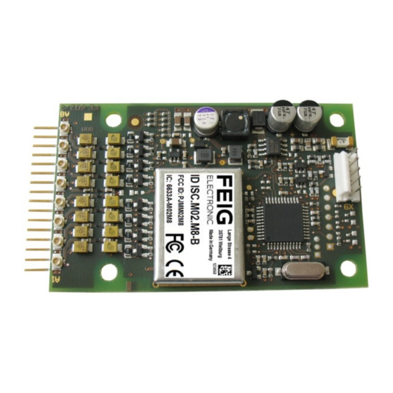
IDENTIFICATION Installation ID ISC.M02.M8 3.2.3 Connection of the external antennas Up to 8 external antennas can be connected. For the connection of the external antennas 8 antenna connectors (X1..X8 respectively A1..A8) are available. The connector type is U.FL-R-SMT from the company Hirose. . -
Page 10: Installation Notes
IDENTIFICATION Installation ID ISC.M02.M8 3.3 Installation notes The reader module has been designed for the installation in a device. 3.3.1 Mounting The reader module can be mounted by using 4mm (M4) screws. Component side: the maximum head diameter should not increase more than 8mm. -
Page 11: Emc Effects On Cables
IDENTIFICATION Installation ID ISC.M02.M8 3.3.3 EMC effects on cables In spite of the internal EMC filters inside the reader, high levels of noise on the supply voltage can result in impairment of the communication between the reader and transponder. When installing an reader module into another device, be sure therefore that a clean, noise-free power supply is used. -
Page 12: Technical Data
IDENTIFICATION Installation ID ISC.M02.M8 Technical Data Mechanical Data without housing Housing Dimensions (W x H x D) 87 x 50 x 14,1 mm (3.43 x 1.97 x 0.56 inch) Weight 24 g 5 Pin multipin connector Type MTA 100 AMP... - Page 13 IDENTIFICATION Installation ID ISC.M02.M8 Ambient Conditions Temperature range - Operation -20°C to +70°C (-4°F to 158°F) - Storage -40°C to +85°C (-40°F to 185°F) 5 – 95% non condensing Humidity Applicable Norms EN 300 330 Radio approval...
-
Page 14: Approvals
1. Approvals 5.1 1.1. Europa (CE) Hereby, FEIG ELECTRONIC GmbH declares that the radio equipment type ID CPR60 is in com- pliance with Directive 2014/53/EU. The full text of the EU declaration of conformity is available at the following internet address: http://www.feig.de/en/downloads-support/declarations-of-conformity.html... -
Page 15: Usa (Fcc) And Canada (Ic)
Warning: Changes or modification made to this equipment not expressly approved by FEIG ELECTRONIC GmbH may void the FCC authorization to operate this equipment. Installation with FCC / IC Approval: The reader module was tested according to the standard FCC - Title 47 CFR Part 15 §207, $209... - Page 16 IDENTIFICATION Installation ID ISC.M02.M8 The manufacturer is obliged to test the terminal device together with the reader module according to the national FCC requirements according to 47 CFR Part15 §209 and §225 For this purpose the reader module must be set to normal operation, ScanMode. The Scan mode...
Need help?
Do you have a question about the ID ISC.M02.M8 and is the answer not in the manual?
Questions and answers