Feig Electronic OBID ID ISC.MRMU102-A Installation Manual
Module version
Hide thumbs
Also See for OBID ID ISC.MRMU102-A:
- User manual (64 pages) ,
- Installation manual (24 pages) ,
- Installation manual (29 pages)

Subscribe to Our Youtube Channel
Related Manuals for Feig Electronic OBID ID ISC.MRMU102-A


Summary of Contents for Feig Electronic OBID ID ISC.MRMU102-A
- Page 1 MONTAGE INSTALLATION ID ISC.MRMU102-A Modul-Variante Module Version (deutsch / english) preliminary public (B) 2012-03-22 M10410-2de-ID-B.doc...
- Page 2 ® OBID i-scan Montage / Installation ID ISC.MRMU102-A Deutsche Version ab Seite 3 English version from page 19 FEIG ELECTRONIC GmbH Seite 2 von 36 M10410-2de-ID-B.doc...
- Page 3 Hinweise jederzeit dankbar. Die in diesem Dokument gemachten Installationsempfehlungen gehen von günstigsten Rahmenbedingun- gen aus. FEIG ELECTRONIC GmbH übernimmt weder Gewähr für die einwandfreie Funktion in system- fremden Umgebungen, noch für die Funktion eines Gesamtsystems, welches die in diesem Dokument be- schriebenen Geräte enthält.
-
Page 4: Table Of Contents
USB – Schnittstelle X3 (Host Kommunikation) ............11 Bedien und Anzeigeelemente LED ..........................12 Technische Daten Funk Zulassungen Europa (CE) ....................... 15 Declaration of Conformity ..................16 Anhang Zubehör ........................17 8.1.1 Serielles Datenkabel ID CAB.RS-A ................ 18 FEIG ELECTRONIC GmbH Seite 4 von 36 M10410-2de-ID-B.doc... - Page 5 Obwohl dieses Gerät die zulässigen Grenzwerte für elektromagnetische Felder nicht über- schreitet, sollten Sie einen Mindestabstand von 25 cm zwischen dem Gerät und Ihrem Herz- schrittmacher einhalten und sich nicht für längere Zeit in unmittelbarer Nähe des Geräts bzw. der Antenne aufhalten. FEIG ELECTRONIC GmbH Seite 5 von 36 M10410-2de-ID-B.doc...
-
Page 6: Leistungsmerkmale Der Readerfamilie Id Isc.mrmu102
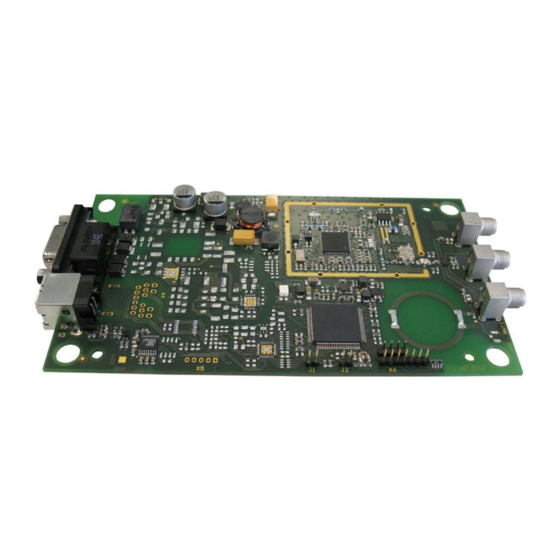
ID ISC.MRMU102-A Modulvariante mit asynchroner RS232- und USB- Schnittstelle 3 x externe Antennenanschlüsse über SMA Buchse 50Ohm 1 x interne Antenne Tabelle 1: Readertypen 2.2 Verfügbares Zubehör optionales Zubehör ist im Anhang aufgeführt: FEIG ELECTRONIC GmbH Seite 6 von 36 M10410-2de-ID-B.doc... -
Page 7: Montage
• Vor der endgültigen Installation sollte der geplante Installationsort auf seine Tauglich- keit geprüft werden. 3.2 Abmessungen 107,5 FE 741 ANT1 ANT2 ANT3 4,75 68,5 Abbildung 1: Abmessungen der Modulvariante (alle Maße in mm) FEIG ELECTRONIC GmbH Seite 7 von 36 M10410-2de-ID-B.doc... -
Page 8: Anschlüsse
Kommunikation mit Fernfeld- als auch mit Nahfeldtranspondern geeignet. Die maximale Lesereichweite beträgt dabei mit einem Fernfeldtransponder ca. 40 cm und mit einem Nahfeldtransponder ca. 5 cm. Abbildung 2: Position der internen Antenne FEIG ELECTRONIC GmbH Seite 8 von 36 M10410-2de-ID-B.doc... -
Page 9: Spannungs- Und Schnittstellenanschluss X2
Tabelle 4: Anschlussbelegung des Steckers X2 Für den Reader ist ein serielles Datenkabel mit integriertem Spannungsanschluss erhältlich. (Siehe Serielles Datenkabel ID CAB.RS-A). Feig Artikel Nr. Bezeichnung 1690.000.00 ID CAB.RS-A Tabelle 5: Serielles Datenkabel FEIG ELECTRONIC GmbH Seite 9 von 36 M10410-2de-ID-B.doc... -
Page 10: Spannungsversorgung
Der Reader muss immer über ein externes Netzteil mit Spannung versorgt werden. 4.3.2 RS232 Schnittstelle Die Übertragungsparameter können per Softwareprotokoll konfiguriert werden. Nähere Informatio- nen sind dem Systemhandbuch H10410-Xe-ID-B.pdf des Lesers zu entnehmen. FEIG ELECTRONIC GmbH Seite 10 von 36 M10410-2de-ID-B.doc... -
Page 11: Usb - Schnittstelle X3 (Host Kommunikation)
Die maximale Länge des USB-Kabels darf 5 m betragen. Längere Kabel sind nicht er- laubt. • Eine Versorgung des Readers mit Spannung über die USB-Leitung ist nicht möglich. Das Gerät muss immer über ein externes Netzteil mit Spannung versorgt werden. FEIG ELECTRONIC GmbH Seite 11 von 36 M10410-2de-ID-B.doc... -
Page 12: Bedien Und Anzeigeelemente
Leuchtet, wenn ein Transponder erkannt wird. LED rot Blinkt bei RF-Warning (rot - grün abwechselnd mit 8Hz) (Temperaturalarm, Kurzschluss am Antennenausgang) „INITIALISIERUNG“ LED orange Blinkt während der Reader-Initialisierung nach dem Ein- schalten. Tabelle 7: Standard-Konfiguration der LED FEIG ELECTRONIC GmbH Seite 12 von 36 M10410-2de-ID-B.doc... -
Page 13: Technische Daten
* Achtung: Eine Überhitzung des Gerätes kann zu Leistungseinbußen führen. Um dies auszuschließen wird empfohlen die RF des Lesers nur dann zu aktivieren, wenn sich ein Transponder im Erfassungsbereich einer Antenne befindet. FEIG ELECTRONIC GmbH Seite 13 von 36 M10410-2de-ID-B.doc... - Page 14 FCC 47 CFR Part 15 - Kanada IC RSS-GEN, RSS-210 • EN 301 489 • Vibration EN60068-2-6 10 Hz bis 150 Hz : 0,075 mm / 1 g • Schock EN60068-2-27 Beschleunigung : 30 g FEIG ELECTRONIC GmbH Seite 14 von 36 M10410-2de-ID-B.doc...
-
Page 15: Funk Zulassungen
Die Funkanlage entspricht, bei bestimmungsgemäßer Verwendung den grundlegenden Anforde- rungen des Artikels 3 und den übrigen einschlägigen Bestimmungen der R&TTE Richtlinie 1999/5/EG vom März 1999. Equipment Classification gemäß ETSI EN 301 489: Class 2 FEIG ELECTRONIC GmbH Seite 15 von 36 M10410-2de-ID-B.doc... -
Page 16: Declaration Of Conformity
® OBID i-scan Montage / Installation ID ISC.MRMU102-A 7.2 Declaration of Conformity FEIG ELECTRONIC GmbH Seite 16 von 36 M10410-2de-ID-B.doc... -
Page 17: Anhang
DC Stecker 2,5mm*5,5mm Output: 12 V DC/ ; 700mA Umgebungstemperatur: 0°C bis +40°C 1690.000.00 ID CAB.RS-A Serielles Datenkabel mit integrierter Versor- gungsleitung 1686.000.00 ID CAB.USB-A USB-Kabel 2,5m Tabelle 8: Zubehör FEIG ELECTRONIC GmbH Seite 17 von 36 M10410-2de-ID-B.doc... -
Page 18: Serielles Datenkabel Id Cab.rs-A
OBID i-scan Montage / Installation ID ISC.MRMU102-A 8.1.1 Serielles Datenkabel ID CAB.RS-A Reader D-Sub 9pol. Stecker D-Sub 9pol. Buchse DC Buchse 2,5 x 5,5mm (aussen) (innen) Abbildung 4: Serielles Datenkabel mit Spannungsanschluss FEIG ELECTRONIC GmbH Seite 18 von 36 M10410-2de-ID-B.doc... - Page 19 FEIG ELECTRONIC GmbH assumes no responsibility for the use of any information contained in this docu- ment and makes no representation that they free of patent infringement. FEIG ELECTRONIC GmbH does not convey any license under its patent rights nor the rights of others.
- Page 20 USB – Interface X3 (Host communication) .............. 28 Control and display elements LED 13.1 LED ..........................29 Technical Data Radio Approvals 15.1 Europe (CE) ....................... 32 15.2 Europe (CE) ....................... 33 15.3 USA (FCC) and Canada (IC) ..................34 FEIG ELECTRONIC GmbH Seite 20 von 36 M10410-2de-ID-B.doc...
- Page 21 ® OBID i-scan Montage / Installation ID ISC.MRMU102-A Annex 16.1 Accessories ......................35 16.1.1 Serial data cable ID CAB.RS-A ................36 FEIG ELECTRONIC GmbH Seite 21 von 36 M10410-2de-ID-B.doc...
- Page 22 Although this device doesn't exceed the valid limits for electromagnetic fields you should keep a minimum distance of 25 cm between the device and your cardiac pacemaker and not stay in the immediate proximity of the device’s antenna for any length of time. FEIG ELECTRONIC GmbH Seite 22 von 36 M10410-2de-ID-B.doc...
-
Page 23: Performance Features Of The Readers
Module version with asynchronous RS232- and USB-Interface; ID ISC.MRMU102-A 3 SMA connectors for external antennas; 1 integrated antenna; Table 1: Reader types 10.2 Optional accessories Optional Accessories are listed in the attachment. FEIG ELECTRONIC GmbH Seite 23 von 36 M10410-2de-ID-B.doc... -
Page 24: Assembly And Wiring
Before any installation the intended position of the reader should be tested for it´s suitability. 11.1.1 Dimensions 107,5 FE 741 ANT1 ANT2 ANT3 4,75 68,5 Figure 1: Dimensions of the module version (all dimensions in mm) FEIG ELECTRONIC GmbH Seite 24 von 36 M10410-2de-ID-B.doc... -
Page 25: Connections
40 cm. In combination with a near field transponder the maximum read range will not increase 5 cm. Figure 2: Position of the internal antenna FEIG ELECTRONIC GmbH Seite 25 von 36 M10410-2de-ID-B.doc... -
Page 26: Power Supply And Interface Connection On X2
Table 4: Connection assignment of the connector X2 For this reader a serial cable with integrated DC connector is available. (See: Serial data cable ID CAB.RS-A). Feig Part No. Description 1690.000.00 ID CAB.RS-A Table 5: Serial data cable FEIG ELECTRONIC GmbH Seite 26 von 36 M10410-2de-ID-B.doc... -
Page 27: Power Supply
The reader always needs to be supplied with an external power supply. 12.3.2 RS232 Interface Interface parameter can be configured via software protocol (e.g. ISOStart). Further information can be found in the System Manual H10410-Xe-ID-B.pdf of the reader. FEIG ELECTRONIC GmbH Seite 27 von 36 M10410-2de-ID-B.doc... -
Page 28: Usb - Interface X3 (Host Communication)
The length of the USB-cable can be a max. of 5 meter. It isn’t allowed to use longer cables! • Powering the reader via the USB cable is not possible. The reader always needs to be supplied with an external power supply. FEIG ELECTRONIC GmbH Seite 28 von 36 M10410-2de-ID-B.doc... -
Page 29: Control And Display Elements Led
Flashes if RF-Warning (red – green alternating with 8Hz) (Temperature alarm, short circuit on antenna output) „INITIALIZING“ LED orange Flashes during Reader initialization after power-up. Table 7: Default configuration of the LEDs FEIG ELECTRONIC GmbH Seite 29 von 36 M10410-2de-ID-B.doc... -
Page 30: Technical Data
* Caution: Overheating of the device may result in performance losses. It is recommended to activate the RF of the reader only if there is a trans- ponder in the detection range of an antenna. FEIG ELECTRONIC GmbH Seite 30 von 36... - Page 31 IC RSS-GEN, RSS-210 - Canada • EMC EN 301 489 • Vibration EN 60068-2-6 10 Hz to 150 Hz : 0,075 mm / 1 g • Shock EN 60068-2-27 Acceleration : 30 g FEIG ELECTRONIC GmbH Seite 31 von 36 M10410-2de-ID-B.doc...
-
Page 32: Radio Approvals
When used according to regulation, this radio equipment conforms with the basic requirements of Article 3 and the other relevant provisions of the R&TTE Guideline 1999/E6 dated March 99. Equipment Classification according to ETSI EN 301 489: Class 2 FEIG ELECTRONIC GmbH Seite 32 von 36 M10410-2de-ID-B.doc... -
Page 33: Europe (Ce)
® OBID i-scan Montage / Installation ID ISC.MRMU102-A 15.2 Europe (CE) FEIG ELECTRONIC GmbH Seite 33 von 36 M10410-2de-ID-B.doc... -
Page 34: Usa (Fcc) And Canada (Ic)
® OBID i-scan Montage / Installation ID ISC.MRMU102-A 15.3 USA (FCC) and Canada (IC) FEIG ELECTRONIC GmbH Seite 34 von 36 M10410-2de-ID-B.doc... - Page 35 DC Plug 2,5mm*5,5mm Output: 12 V DC/ ; 700mA Ambient Operating Temperature: 0°C to +40°C 1690.000.00 ID CAB.RS-A Serial data cable with integrated supply voltage line 1686.000.00 ID CAB.USB-A USB-Cable 2,5m Table 8: Accessories FEIG ELECTRONIC GmbH Seite 35 von 36 M10410-2de-ID-B.doc...
- Page 36 Montage / Installation ID ISC.MRMU102-A 16.1.1 Serial data cable ID CAB.RS-A Reader D-Sub 9pol. male D-Sub 9pol. female DC Jack 2,5 x 5,5mm (outside) (inside) Figure 4: Serial data cable with supply voltage connection FEIG ELECTRONIC GmbH Seite 36 von 36 M10410-2de-ID-B.doc...
Need help?
Do you have a question about the OBID ID ISC.MRMU102-A and is the answer not in the manual?
Questions and answers