
Related Manuals for Feig Electronic ID ISC.MU02.02


Summary of Contents for Feig Electronic ID ISC.MU02.02
- Page 1 INSTALLATION ID ISC.MU02.02 UHF Reader Module final – public (B) 2018-09-19 – M91002-5e-ID-B.docx...
- Page 2 FEIG ELECTRONIC call explicit attention that devices which are subject of this document are not designed with components and testing methods for a level of reliability suitable for use in or in connection with surgical implants or as critical components in any life support systems whose failure to perform can reasonably be expected to cause significant injury to a human.
- Page 3 Identification Installation ID ISC.MU02.02 General information's regarding this document The sign "" indicates extensions or changes of this manual compared with the former issue. If bits within one byte are filled with "-", these bit spaces are reserved for future extensions or for internal testing- and manufacturing-functions.
-
Page 4: Table Of Contents
Installation ID ISC.MU02.02 Contents 1. Safety Instructions / Warning - Read before start-up ! 2. Performance Characteristics of the ID ISC.MU02.02 Reader Module 2.1. Performance Characteristics .................... 7 2.2. Available module types ..................... 7 2.3. Optional available ......................8 3. Installation and wiring 3.1. - Page 5 Identification Installation ID ISC.MU02.02 5.2.4. USA (FCC) and Canada (IC) approved antennas ............22 FEIG ELECTRONIC GmbH Page 5 of 22 M91002-5e-ID-B.docx...
- Page 6 Identification Installation ID ISC.MU02.02 1. Safety Instructions / Warning - Read before start-up ! The device may only be used for the intended purpose designed by for the manufacturer. The operation manual should be conveniently kept available at all times for each user.
-
Page 7: Performance Characteristics Of The Id Isc.mu02.02 Reader Module
2. Performance Characteristics of the ID ISC.MU02.02 Reader Module 2.1. Performance Characteristics The ID ISC.MU02.02 Reader Module is designed for reading and writing passive transponders, so- called “Smart Labels”, with an operating frequency of 860 MHz to 960 MHz. It is suitable for any application in which short and middle read ranges and small reader dimensions are required. -
Page 8: Optional Available
Identification Installation ID ISC.MU02.02 2.3. Optional available The following components are optional available for the ID ISC.MU02.02. Table 2: Accessories Accessories Order number For COM-Port connection: ID CAB.A-A Cable for Adaption of RS232 and Data/Clock 2259.000.00 ID CAB.RS-A Cable for RS232 and Power supply 1690.000.00... -
Page 9: Installation And Wiring
Installation ID ISC.MU02.02 3. Installation and wiring 3.1. Dimensions Figure 1 shows the dimensions of the ID ISC.MU02.02 Reader Module in mm. Figure 1: Dimensions of the ID ISC.MU02.02 Reader Module in mm FEIG ELECTRONIC GmbH Page 9 of 22... -
Page 10: Wiring - Connector X2
Identification Installation ID ISC.MU02.02 3.2. Wiring – Connector X2 Figure 2 and Table 1 show the pin assignments for Terminal X2. The pin connector is designed for flat cable connection using an IDC multipoint socket connector with 2.54 mm pin spacing. -
Page 11: Supply Voltage
ID ISC.MU02.02 3.2.1. Supply voltage The ID ISC.MU02.02 must be supplied only by a regulated power supply. If switching power sup- plies are used with the module, be sure that there is adequate filtering. Noise from the power sup- ply can result in a reduction of the read/write range of the module. The cable length from the power supply should be as short as possible, and should in any case not exceed 3 m. -
Page 12: Data/Clock Interface
Identification Installation ID ISC.MU02.02 The transmission parameters for the interface can be software-configured. Table 6 shows the standard parameters for the RS232 interface. Table 6: Standard parameters of the RS232 interface Parameter Standard setting Baud rate 38400 No. of data bits... -
Page 13: Shut Down
Installation ID ISC.MU02.02 3.2.4. Shut Down The ID ISC.MU02.02 can be switched off with the SHDN pin (pin no. 6 at terminal X2). Therefor the pin has to be connected to Ground. Table 8: Status table for the SHDN pin Operating status Pin no. -
Page 14: Usb Interface
For this the instruction "M70700-xde-ID-B: Installation OBID USB driver" can be used. NOTE: If the ID ISC.MU02.02 is USB powered there MUST NOT connected a power supply to termi- nal X2. FEIG ELECTRONIC GmbH Page 14 of 22... -
Page 15: Antenna Ports
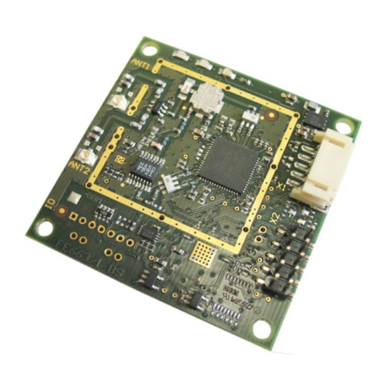
ID ISC.MU02.02 3.4. Antenna ports There can be 2 antennas connected to the ID ISC.MU02.02 at the antenna ports ANT1 and ANT2. Figure 5 shows the position of the “Hirose U.FL” receptacles with an input impedance of 50 Ω. The antennas can be switched by software. -
Page 16: Display Elements
Installation ID ISC.MU02.02 3.5. Display elements The ID ISC.MU02.02 Reader Module has a red LED (V1) and a green LED (V2) and a blue LED (V3) which are used as display elements (Figure 6). Figure 6: Position of the LEDs The functions of both LEDs V2 and V3 can be configured using software protocol. -
Page 17: Installation Notes
Impaired communication between reader and transponder 3.6.1. Metallic surroundings When installing an ID ISC.MU02.02 into another device, be sure that there are no metal surfaces or objects in the direct vicinity of the connected antennas if possible. These can detune the anten- na and impair the propagation of the electromagnetic field due to reflections. -
Page 18: Technical Data
860 MHz to 960 MHz RF-Power max. 170 mW, configurable 2 x “Hirose U.FL” receptacles, 50 Ω; internal Antenna Connection Multiplexer Interfaces ID ISC.MU02.02-AD RS232-V24, Data/Clock ID ISC.MU02.02-CU RS232-LVTTL, USB FUNCTIONAL PROPERTIES Protocol Modes FEIG ISO HOST Mode (Advanced Protocol Frame) ... - Page 19 Identification Installation ID ISC.MU02.02 AMBIENT CONDITIONS Temperature Range Operation -25 °C to +55 °C (-13°F to 131 °F) Storage -25 °C to +85 °C (-13°F to 185 °F) Humidity 5 % to 95 % non-condensing APPLICABLE STANDARDS Radio Regulation ...
-
Page 20: Radio Approvals
5. Radio Approvals 5.1. Europe (CE) Hereby, FEIG ELECTRONIC GmbH declares that the radio equipment type ID CPR74 is in com- pliance with Directive 2014/53/EU. The full text of the EU declaration of conformity is available at the following internet address: http://www.feig.de/en/downloads-support/declarations-of-conformity.html... -
Page 21: Usa (Fcc) And Canada (Ic)
Warning: Changes or modification made to this equipment not expressly approved by FEIG ELECTRONIC GmbH may void the FCC authorization to operate this equipment. FEIG ELECTRONIC GmbH Page 21 of 22... -
Page 22: Label Information
Identification Installation ID ISC.MU02.02 5.2.2. Label Information The following information must be placed at the outer side of the housing in which the reader is mounted. Contains FCC ID PJMMU02 Contains IC: 6633A-MU02 5.2.3. Installation with FCC / IC Approval...
Need help?
Do you have a question about the ID ISC.MU02.02 and is the answer not in the manual?
Questions and answers