
Related Manuals for Feig Electronic OBID i-scan D ISC.MU02.02


Summary of Contents for Feig Electronic OBID i-scan D ISC.MU02.02
- Page 1 MONTAGE ® OBID i-scan INSTALLATION ID ISC.MU02.02 (deutsch / english) final public (B) 2010-02-12 M91002-0de-ID-B.doc...
- Page 2 ® OBID i-scan Montage ID ISC.MU02.02 deutsche Version ab Seite 3 english version from page 20 FEIG ELECTRONIC GmbH Page 2 of 36 M91002-0de-ID-B.doc...
- Page 3 Hinweise jederzeit dankbar. Die in diesem Dokument gemachten Installationsempfehlungen gehen von günstigsten Rahmenbedingun- gen aus. FEIG ELECTRONIC GmbH übernimmt weder Gewähr für die einwandfreie Funktion in system- fremden Umgebungen, noch für die Funktion eines Gesamtsystems, welches die in diesem Dokument be- schriebenen Geräte enthält.
-
Page 4: Table Of Contents
3.3. Anschluss USB-Schnittstelle X1..................12 3.4. Antennenanschluss ......................13 3.5. Anzeigeelemente .......................14 3.6. Montagehinweise ......................15 3.6.1. Metallische Umgebung ....................15 3.6.2. EMV-Beeinflussung über Zuleitungen .................16 4. Funkzulassungen 4.1. Europa (CE)........................16 4.2. USA (FCC) ..........................17 5. Technische Daten FEIG ELECTRONIC GmbH Page 4 of 36 M91002-0de-ID-B.doc... -
Page 5: Sicherheits- Und Warnhinweise - Vor Inbetriebnahme Unbedingt Lesen
Besonderer Hinweis für Träger von Herzschrittmachern: Obwohl dieses Gerät die zulässigen Grenzwerte für elektromagnetische Felder nicht über- schreitet, sollten Sie einen Mindestabstand von 25 cm zwischen dem Gerät und Ihrem Herz- schrittmacher einhalten. FEIG ELECTRONIC GmbH Page 5 of 36 M91002-0de-ID-B.doc... -
Page 6: Leistungsmerkmale Des Readermoduls Id Isc.mu02.02
ID Net.5V Netzteil 1689.000.00.01 ID CAB.USB-B Kabel für USB 3541.000.00.00 ID ISC.ANT.C05-A UHF-Antennenkabel U.FL-U.FL 500 mm 3540.000.00.00 ID ISC.ANT.U75/50-EU UHF-Antennenmodul 865 – 868 MHz 3544.000.00.00 ID ISC.ANT.U75/50-FCC UHF-Antennenmodul 902 – 928 MHz 3543.000.00.00 FEIG ELECTRONIC GmbH Page 6 of 36 M91002-0de-ID-B.doc... -
Page 7: Montage Und Anschluss
OBID i-scan Montage ID ISC.MU02.02 3. Montage und Anschluss 3.1. Abmessungen zeigt die Maßzeichnung des Readermoduls ID ISC.MU02.02 in mm. Bild 1 Bild 1 : Maßzeichnung des Readermoduls ID ISC.MU02.02 in mm FEIG ELECTRONIC GmbH Page 7 of 36 M91002-0de-ID-B.doc... -
Page 8: Anschluss Rs232- Und Daten-/Takt-Schnittstelle X2
GND ** Masse Keine Funktion (NUR offen betreiben!) Nur geregelte DC-Spannungen verwenden ! Die GND-Pins 4 und 9 sind auf dem Readermodul direkt miteinander verbunden Tabelle 1 : Belegung der Anschlussstiftleiste X2 FEIG ELECTRONIC GmbH Page 8 of 36 M91002-0de-ID-B.doc... -
Page 9: Spannungsversorgung
Tabelle 2 : Pinbelegung der Spannungsversorgung an X2 HINWEIS: • Eine Verpolung der Versorgungsspannung kann zur Zerstörung des Gerätes führen. • Versorgungsspannungen außerhalb der Spezifikation können zur Zerstörung des Gerä- tes führen. FEIG ELECTRONIC GmbH Page 9 of 36 M91002-0de-ID-B.doc... -
Page 10: Rs232-Schnittstelle
COM-Port Parameter „Char Timeout Multiplier“ von „1“ auf ca. „10“ erhöht werden. • Wird ein RS232 / TTL-Konverter ohne externe Spannungsversorgung benutzt, kann es notwendig sein das die COM -Port Parameter “RTS” und “DTR” manuell eingeschaltet werden müssen. FEIG ELECTRONIC GmbH Page 10 of 36 M91002-0de-ID-B.doc... -
Page 11: Daten-/Taktschnittstelle
Masse Die GND-Pins 4 und 9 sind auf dem Readermodul direkt miteinander verbunden Tabelle 5 : Pinbelegung der Daten-/Takt-Schnittstelle an X2 Data Clock Host ID ISC.MU02 Bild 3 : Anschluss der Daten-/Taktschnittstelle FEIG ELECTRONIC GmbH Page 11 of 36 M91002-0de-ID-B.doc... -
Page 12: Abschaltung
3.3. Anschluss USB-Schnittstelle X1 Bild 4 und Tabelle 7 zeigen die Belegung des Anschlusssteckers X1 vom Typ “JST PH” Raster- maß 2 mm (liegend). Bild 4: Belegung der Anschlussstiftleiste X1 FEIG ELECTRONIC GmbH Page 12 of 36 M91002-0de-ID-B.doc... -
Page 13: Antennenanschluss
Bild 5 zeigt die Position der Antennenbuchsen vom Typ “Hirose U.FL”. Die Eingangsimpedanz der Buchsen beträgt 50 Ω. Die Antennen können per Software umgeschaltet werden. Bild 5: Position der Antennenbuchsen ANT1 und ANT2 FEIG ELECTRONIC GmbH Page 13 of 36 M91002-0de-ID-B.doc... -
Page 14: Anzeigeelemente
Die Funktionen der beiden LED´s V2 und V3 können per Softwareprotokoll konfiguriert werden. Ergänzend dazu besteht auch die Möglichkeit alle 3 LED´s direkt durch ein weiteres Softwareprotokoll anzusteuern. Tabelle 8 zeigt die Standardeinstellung von V1, V2 und V3. FEIG ELECTRONIC GmbH Page 14 of 36 M91002-0de-ID-B.doc... -
Page 15: Montagehinweise
Leiterplatten, je nach Kupferauflage, wie Me- tallflächen verhalten. Ist eine metallische Umgebung nicht zu vermeiden, so sollten die Abstände im Interesse der sta- bilen Funktion jedoch so groß wie nur irgend möglich gewählt werden. FEIG ELECTRONIC GmbH Page 15 of 36 M91002-0de-ID-B.doc... -
Page 16: Emv-Beeinflussung Über Zuleitungen
Die Funkanlage entspricht, bei bestimmungsgemäßer Verwendung den grundlegenden Anforde- rungen des Artikels 3 und den übrigen einschlägigen Bestimmungen der R&TTE Richtlinie 1999/5/E6 vom März 99. Equipment Classification gemäß ETSI EN 301 489: Class 2 FEIG ELECTRONIC GmbH Page 16 of 36 M91002-0de-ID-B.doc... -
Page 17: Usa (Fcc)
Changes or modifications made to this equipment not expressly approved by FEIG ELECTRONIC GmbH may void the FCC authorization to operate this equipment. This equipment has been tested and found to comply with the limits for a Class B digital device, pursuant to Part 15 of the FCC Rules. -
Page 18: Technische Daten
860 ... 960 MHz Betriebsfrequenz • max. 170mW; reduzierbar Sendeleistung • Antennenanschluss 2 Buchsen vom Typ „Hirose U.FL“; 50 Ω; um- schaltbar • Schnittstellen RS232-V24, Daten-/Takt Variante AD RS232-LVTTL, USB Variante CU FEIG ELECTRONIC GmbH Page 18 of 36 M91002-0de-ID-B.doc... - Page 19 5 bis 95% nicht betauend Relative Luftfeuchtigkeit Angewendete Normen • Zulassung Funk EN 302 208 - Europa FCC 47 CFR Part 15 - USA • EN 301 489 • EN 60950 Sicherheit FEIG ELECTRONIC GmbH Page 19 of 36 M91002-0de-ID-B.doc...
- Page 20 FEIG ELECTRONIC call explicit attention that devices which are subject of this document are not designed with components and testing methods for a level of reliability suitable for use in or in connection with surgical implants or as critical components in any life support systems whose failure to perform can reasonably be expected to cause significant injury to a human.
- Page 21 8.4. Antenna ports ........................30 8.5. Display elements .......................31 8.6. Installation notes.......................32 8.6.1. Metallic surroundings....................32 8.6.2. EMC effects on cables....................33 9. Radio Approvals 9.1. Europe (CE)........................33 9.2. USA (FCC) ..........................34 10. Technical Data FEIG ELECTRONIC GmbH Page 21 of 36 M91002-0de-ID-B.doc...
- Page 22 Special advice for carriers of cardiac pacemakers: Although this device doesn't exceed the valid limits for electromagnetic fields you should keep a minimum distance of 25 cm between the device and your cardiac pacemaker. FEIG ELECTRONIC GmbH Page 22 of 36 M91002-0de-ID-B.doc...
-
Page 23: Performance Characteristics Of The Id Isc.mu02.02 Reader Module
ID CAB.USB-B Cable for USB 3541.000.00.00 ID ISC.ANT.C05-A UHF antenna cable U.FL-U.FL 500 mm 3540.000.00.00 ID ISC.ANT.U75/50-EU UHF antenna module 865 – 868 MHz 3544.000.00.00 ID ISC.ANT.U75/50-FCC UHF antenna module 902 – 928 MHz 3543.000.00.00 FEIG ELECTRONIC GmbH Page 23 of 36 M91002-0de-ID-B.doc... -
Page 24: Installation And Wiring
ID ISC.MU02.02 8. Installation and wiring 8.1. Dimensions Fig. 1 shows the dimensions of the ID ISC.MU02.02 Reader Module in mm. Fig. 1 : Dimensions of the ID ISC.MU02.02 Reader Module in mm FEIG ELECTRONIC GmbH Page 24 of 36 M91002-0de-ID-B.doc... -
Page 25: Wiring
(use ONLY open!) Use only regulated DC power supplies ! GND-Pins 4 and 9 are to be connected directly to each other on the Reader Module Table 1 : Pin assignments for Terminal X2 FEIG ELECTRONIC GmbH Page 25 of 36 M91002-0de-ID-B.doc... -
Page 26: Supply Voltage
Reader Module Table 2 : Pin assignments for X2 NOTE: • Reversing the polarity of the supply voltage may destroy the device. • Supply voltages outside the specifications may destroy the device. FEIG ELECTRONIC GmbH Page 26 of 36 M91002-0de-ID-B.doc... -
Page 27: Rs232 Interface
„10“. • IF there is a RS232 to TTL converter used without external power supply it may be nec- essary to switch on the COM Port parameter “RTS” and “DTR” manually. FEIG ELECTRONIC GmbH Page 27 of 36 M91002-0de-ID-B.doc... -
Page 28: Data/Clock Interface
GND-Pins 4 and 9 are to be connected directly to each other on the Reader Module Table 5 : Pin configuration for the RS232 interface on Terminal X2 Data Clock Host ID ISC.MU02 Fig. 3 : Connecting the data/clock interface FEIG ELECTRONIC GmbH Page 28 of 36 M91002-0de-ID-B.doc... -
Page 29: Shut Down
• Supply voltages outside the specifications may destroy the device. 8.3. USB interface Fig. 4 and Table 7 show the pin assignments for Terminal X1 (“JST PH” type with pitch 2.0 mm). Fig. 7: Pin assignments for Terminal FEIG ELECTRONIC GmbH Page 29 of 36 M91002-0de-ID-B.doc... -
Page 30: Antenna Ports
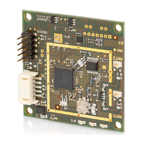
There can be 2 antennas connected to the ID ISC.MU02.02 at the antenna ports ANT1 and ANT2. Fig. 5 shows the position of the “Hirose U.FL” receptacles with an input impedance of 50 Ω. The antennas can be switched by software. Fig. 5: Antenna ports ANT1 and ANT2 FEIG ELECTRONIC GmbH Page 30 of 36 M91002-0de-ID-B.doc... -
Page 31: Display Elements
: Position of the LEDs The functions of both LEDs V2 and V3 can be configured using software protocol. It is also possi- ble to control all 3 LEDs directly using an additional software protocol. FEIG ELECTRONIC GmbH Page 31 of 36 M91002-0de-ID-B.doc... -
Page 32: Installation Notes
The distance between the antennas and a metal surface should be at least 5 cm. Note that even other circuit boards may act line metal objects depending on how much copper they contain. FEIG ELECTRONIC GmbH Page 32 of 36 M91002-0de-ID-B.doc... -
Page 33: Emc Effects On Cables
When used according to regulation, this radio equipment conforms with the basic requirements of Article 3 and the other relevant provisions of the R&TTE Guideline 1999/5/E6 dated March 99. Equipment Classification gemäß ETSI EN 301 489: Class 2 FEIG ELECTRONIC GmbH Page 33 of 36 M91002-0de-ID-B.doc... -
Page 34: Usa (Fcc)
Changes or modifications made to this equipment not expressly approved by FEIG ELECTRONIC GmbH may void the FCC authorization to operate this equipment. This equipment has been tested and found to comply with the limits for a Class B digital device, pursuant to Part 15 of the FCC Rules. -
Page 35: Technical Data
860 ... 960 MHz Operating frequency • max. 170 mW ; reducible Transmitting power • Antenna connection 2 x “Hirose U.FL” receptacles; 50 Ω; switchable • Interfaces RS232-V24, Data/Clock Variant AD RS232-LVTTL, USB Variant CU FEIG ELECTRONIC GmbH Page 35 of 36 M91002-0de-ID-B.doc... - Page 36 • 5 – 95% non condensing Humidity Applicable Norms • Radio approval EN 302 208 - Europe FCC 47 CFR Part 15 - USA • EN 301 489 • EN 60950 Safety FEIG ELECTRONIC GmbH Page 36 of 36 M91002-0de-ID-B.doc...
Need help?
Do you have a question about the OBID i-scan D ISC.MU02.02 and is the answer not in the manual?
Questions and answers