
Subscribe to Our Youtube Channel
Related Manuals for Feig Electronic OBID i-scan ID ISC.M02.M8-B


Summary of Contents for Feig Electronic OBID i-scan ID ISC.M02.M8-B
- Page 1 INSTALLATION MANUAL ID ISC.M02.M8-B (English) final – public (B) 2013-02-18 – M90402-1e-ID-B...
- Page 2 FEIG ELECTRONIC call explicit attention that devices which are subject of this document are not designed with components and testing methods for a level of reliability suitable for use in or in connection with surgical implants or as critical components in any life support systems whose failure to perform can reasonably be expected to cause significant injury to a human.
-
Page 3: Table Of Contents
Installation notes ....................10 3.3.1 Mounting ........................ 10 3.3.2 Influence ........................ 10 3.3.3 EMC effects on cables ................... 11 3.3.4 EMC effects from magnetic fields ................11 Technical Data Radio Approvals Europe (CE) ......................14 FEIG ELECTRONIC GmbH Page 3 of 15 M90402-1e-ID-B... - Page 4 Although this device doesn't exceed the valid limits for electromagnetic fields you should keep a minimum distance of 25 cm between the device and your cardiac pacemaker and not stay in the immediate proximity of the device’s antenna for any length of time. FEIG ELECTRONIC GmbH Page 4 of 15 M90402-1e-ID-B...
-
Page 5: Performance Characteristics Of The Id Isc.m02.M8-B Reader Module
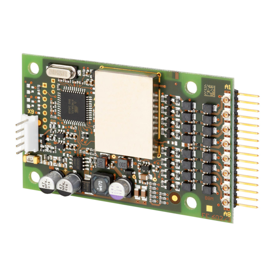
The module has an integrated antenna multiplexer. Up to 8 external antennas can be connected. 2.2 Available module The following reader types are available: Module type Description ID ISC.M02.M8-B 1 x Reader module ID ISC.M02.M8-B Table 1: Available module version FEIG ELECTRONIC GmbH Page 5 of 15 M90402-1e-ID-B... -
Page 6: Installation And Wiring
Installation and wiring 3.1 Dimensions Fig. 1 shows the dimensions of the ID ISC.M02.M8-B Reader Module in mm. 87±0,3 80±0,3 65±0,3 5±0,3 4±0,3 Fig. 1 : Dimension of the Readermodul ID ISC.M02.M8-B FEIG ELECTRONIC GmbH Page 6 of 15 M90402-1e-ID-B... -
Page 7: Wiring
The cable length from the power supply should be as short as possible, and should in any case not exceed 1 m. Note: A wrong polarity of the DC voltage will destroy the reader Supply voltages outside the specifications may destroy the device. FEIG ELECTRONIC GmbH Page 7 of 15 M90402-1e-ID-B... -
Page 8: Rs232-Lvttl-Interface (3,3V)
Table 3 shows the standard parameters for the RS232 interface. Parameter Default Setting Baudrate 38400 bit/s Number of Data bits Parity Even Number of Stop bits Table 3 Default parameter of the RS232 LVTTL FEIG ELECTRONIC GmbH Page 8 of 15 M90402-1e-ID-B... -
Page 9: Connection Of The External Antennas
The ultraminiatur coax connector can be used for up to about 20 connection cycles. For the disconnection the „Extraction Tool“ must be use according to the recommendation from the manufacturer. FEIG ELECTRONIC GmbH Page 9 of 15 M90402-1e-ID-B... -
Page 10: Installation Notes
Impaired propagation of the antenna’s magnetic field EMC effects on cables Impaired communication between reader and transponder EMC effects from magnetic fields Impaired communication between reader and transponder FEIG ELECTRONIC GmbH Page 10 of 15 M90402-1e-ID-B... -
Page 11: Emc Effects On Cables
When determining the position of the reader and antenna within a device, check the device for any possible sources of interference as described above. If necessary, use shielding to suppress such interference. FEIG ELECTRONIC GmbH Page 11 of 15 M90402-1e-ID-B... -
Page 12: Technical Data
Interface Functional Properties Protocol Modes - FEIG ISO HOST ISO15693 Supported transponders EEPROM (for parameters) 1kB (10.000 write cycles) FLASH 64 kB (Firmware Update via interface possible) FEIG ELECTRONIC GmbH Page 12 of 15 M90402-1e-ID-B... - Page 13 - Storage -40°C to +85°C (-40°F to 185°F) 5 – 95% non condensing Humidity Applicable Norms Radio approval - Europe EN 300 330 EN 301 489 Safety EN 60950 FEIG ELECTRONIC GmbH Page 13 of 15 M90402-1e-ID-B...
-
Page 14: Radio Approvals
® OBID i-scan Installation ID ISC.M02.M8-B Radio Approvals 5.1 Europe (CE) FEIG ELECTRONIC GmbH Page 14 of 15 M90402-1e-ID-B... - Page 15 When used according to regulation, this radio equipment conforms with the basic requirements of Article 3 and the other relevant provisions of the R&TTE Guideline 1999/E6 dated March 99. Equipment Classification gemäß ETSI EN 300 330: Class 2 FEIG ELECTRONIC GmbH Page 15 of 15 M90402-1e-ID-B...
Need help?
Do you have a question about the OBID i-scan ID ISC.M02.M8-B and is the answer not in the manual?
Questions and answers