WEG CFW500 Series Installation, Configuration And Operations Manual
Rs485 communication plug-in module
Hide thumbs
Also See for CFW500 Series:
- Installation, configuration and operations manual (20 pages) ,
- Installation, configuration and operations manual (24 pages) ,
- Safety manual (81 pages)
Table of Contents
Advertisement
Available languages
Available languages
Quick Links
Motors | Automation | Energy | Transmission & Distribution | Coatings
RS485 Communication
Plug-in Module
Módulo Plug-in
Comunicación RS485
Módulo Plug-in
Comunicação RS485
CFW500
Installation, Configuration and Operation Guide
Guía de Instalación, Configuración y Operación
Guia de Instalação, Configuração e Operação
Advertisement
Table of Contents

Related Manuals for WEG CFW500 Series


Summary of Contents for WEG CFW500 Series
- Page 1 Motors | Automation | Energy | Transmission & Distribution | Coatings RS485 Communication Plug-in Module Módulo Plug-in Comunicación RS485 Módulo Plug-in Comunicação RS485 CFW500 Installation, Configuration and Operation Guide Guía de Instalación, Configuración y Operación Guia de Instalação, Configuração e Operação...
-
Page 3: Table Of Contents
Summary / Índice SUMMARY 1 SAFETY INFORMATION .......5 1.1 SAFETY WARNINGS ........5 1.2 PRELIMINARY RECOMMENDATIONS ..5 2 GENERAL INFORMATION ......5 3 CONTENTS OF THE PACKAGE ....5 4 ACCESSORY INSTALLATION ....6 5 SETTINGS ............7 APPENDIX A – FIGURES .......20 ÍNDICE 1 INFORMACIONES DE SEGURIDAD ..10 1.1 AVISOS DE SEGURIDAD ...... -
Page 5: Safety Information
RS485 Communication Plug-in Module 1 SAFETY INFORMATION 1.1 SAFETY WARNINGS NOTE! Only use the CFW500-CRS485 Plug-in „ Module in CFW500 WEG inverters. We recommend reading the CFW500 „ user’s manual before installing or operating this accessory. This guide contains important information „... -
Page 6: Accessory Installation
RS485 Communication Plug-in Module 4 ACCESSORY INSTALLATION The accessory is easily installed or replaced. For correct installation of the accessory execute the following steps: Step 1: With the inverter power supply off, remove the front cover of the Inverter (figureA.1 (a)). -
Page 7: Settings
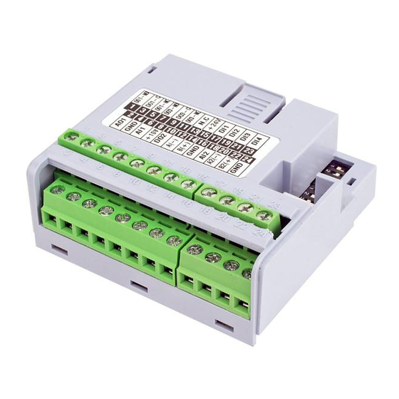
RS485 Communication Plug-in Module 5 SETTINGS The control connections (analogical input / output, digital inputs / outputs and RS485 interface) must be performed as shown in figure Connector Description Digital output 1 DO1-RL-NO (NO contact of relay 1) Digital output 1 DO1-RL-C (common point of relay 1) Digital output 1... - Page 8 RS485 Communication Plug-in Module +24 V The location of the DIP-switches for selecting the type of analog input and output signal and termination of the RS485 line can be better visualized in figure A.2. To use the analog inputs and/ or outputs with signal in current, switch S1 and related parameters must be set as indicated in table...
- Page 9 RS485 Communication Plug-in Module NOTE! Configurations for activation of RS485: „ S1.3 = ON and S1.4 = ON: RS485 „ termination ON S1.3 = OFF and S1.4 = OFF: RS485 „ termination OFF Any other combinations of the switches are not allowed NOTE! C o n f i g u r ati o n s fo r a c ti vati o n of „...
-
Page 10: Informaciones De Seguridad
1.1 AVISOS DE SEGURIDAD ¡NOTA! Solamente utilice el Módulo Plug-in „ CFW500-CRS485 en los convertidores WEG línea CFW500. Se recomienda la lectura del manual „ del usuario del CFW500 antes de instalar u operar este accesorio. El contenido de esta guía fornece „... -
Page 11: Instalación Del Accesorio
Módulo Plug-in Comunicación RS485 4 INSTALACIÓN DEL ACCESORIO El accesorio es fácilmente instalado o sustituido. Para la correcta instalación del accesorio, ejecute los pasos a seguir: Paso 1: Con el convertidor desenergizado, retire la tapa frontal del mismo (figura A.1 (a)). -
Page 12: Configuraciones
Módulo Plug-in Comunicación RS485 5 CONFIGURACIONES Las conexiones de control (entrada/salida analógica, entradas/salidas digitales e interfaz RS485) deben ser hechas en el conector conforme figura Conector Descripción Salida digital 1 (contacto NA DO1-RL-NO del relé 1) Salida digital 1 (punto común DO1-RL-C del relé... - Page 13 Módulo Plug-in Comunicación RS485 +24 V La localización de las DIP-switches para selección del tipo de señal de la entrada y salida analógica y de la terminación de la red RS485 pueden ser mejor visualizadas en la figura A.2. Para utilizar las entradas y/u salidas analógicas con señal en corriente, se debe ajustar la llave S1 y los parámetros relacionados conforme...
- Page 14 Módulo Plug-in Comunicación RS485 ¡NOTA! Configuraciones para encendido de „ la RS485: S1.3 = ON y S1.4 = ON: terminación „ RS485 encendida S1.3 = OFF y S1.4 = OFF: terminación „ RS485 apagada Cualquier otra combinación de las claves no es permitida ¡NOTA! Configuraciones para encendido de...
-
Page 15: Informações De Segurança
1.1 AVISOS DE SEGURANÇA NOTA! Somente utilizar o Módulo Plug-in „ CF W500-CRS485 nos inversores WEG linha CFW500. Recomenda-se a leitura do Manual do „ Usuário do CFW500 antes de instalar ou operar esse acessório. O c o nte ú d o d e ste g u i a fo r n e c e „... -
Page 16: Instalação Do Acessório
Módulo Plug-in Comunicação RS485 4 INSTALAÇÃO DO ACESSÓRIO O acessório é facilmente instalado ou substituído. Para a correta instalação do acessório execute os passos a seguir: Passo 1: Com o inversor desenergizado, retire a tampa frontal do Inversor (figura A.1 (a)). -
Page 17: Configurações
Módulo Plug-in Comunicação RS485 5 CONFIGURAÇÕES As conexões de controle (entrada/saída analógica, entradas/saídas digitais e interface RS485) devem ser feitas no conector conforme figura Conector Descrição Saída Digital 1 DO1-RL-NO (contato NA do Relé 1) Saída Digital 1 DO1-RL-C (Ponto comum do Relé 1) Saída Digital 1 DO1-RL-NC (Contato NF do Relé... - Page 18 Módulo Plug-in Comunicação RS485 +24 V A localização das DIP-switches para seleção do tipo de sinal da entrada e saída analógica e da terminação da rede RS485 podem ser melhor visualizadas na figura A.2. Para utilizar as entradas e/ou saídas analógicas com sinal em corrente deve-se ajustar a chave S1 e os parâmetros relacionados conforme tabela...
- Page 19 Módulo Plug-in Comunicação RS485 NOTA! Configurações para ligação da RS485: „ S1.3 = ON e S1.4 = ON: terminação „ RS485 ligada S1.3 = OFF e S1.4 = OFF: terminação „ RS485 desligada Qualquer outra combinação das chaves não é permitida NOTA! C o n f i g u r a ç...
-
Page 20: Appendix A - Figures
Appendix A - Anexo A APPENDIX A – FIGURES ANEXO A – FIGURAS a) Removal of front cover and accessory (a) Remoción de la tapa frontal y del accesorio (a) Remoção da tampa frontal e de acessório b) Accessory connection (b) Conexión del accesorio (b) Conexão de acessório Figure A.1 (a) to (b): Installation of accessory... - Page 21 Appendix A - Anexo A 1 3 5 7 9 1113 15 500-CUSB 2 4 6 8 10 1214 16 1 3 5 7 9 1113 15 1719 2123 500-CRS485 2 4 6 8 10 1214 16 18 2022 24 1 3 5 7 9 11 13 500-CCAN 2 4 6 8 10 1214...
- Page 22 NOTES / NOTAS / ANOTAÇÕES...
- Page 24 WEG Drives & Controls - Automação LTDA. Jaraguá do Sul - SC - Brazil Phone 55 (47) 3276-4000 - Fax 55 (47) 3276-4020 São Paulo - SP - Brazil Phone 55 (11) 5053-2300 - Fax 55 (11) 5052-4212 automacao@weg.net 11771108...
Need help?
Do you have a question about the CFW500 Series and is the answer not in the manual?
Questions and answers