Table of Contents
Advertisement
Advertisement
Table of Contents

Subscribe to Our Youtube Channel
Related Manuals for BUSCH COBRA DS 0080 G


Summary of Contents for BUSCH COBRA DS 0080 G
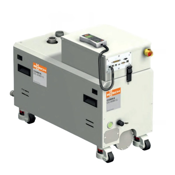
- Page 1 Installation and Maintenance Instructions Screw Vacuum Pumps COBRA DS 0080 - 2000 G Busch Manufacturing Korea, Ltd. 189-51, Soicheon-ro, Majang-myun Icheon-si, Gyunggi-do, 467-813 Republic of Korea 0870772712 / 181024 / Original instructions / Subject to change without notice...
-
Page 2: Table Of Contents
Equipment connections (with options) ... . 15 Congratulations on your purchase of the Busch vacuum pump. With Connection of the lines/ pipes ....15 watchful observation of the field’s requirements, innovation and steady... - Page 3 IN CAO COBRA DS 0080/ 0160 G Inlet OUT Discharge CAO Extracting ventilator RC LCD ES Emergency stop button (EMO) PRV Nitrogen pressure reducer EC Electrical connections EB Eye bolts PMR Unblocking for screw OSG1 Oil sight glass OFP Oil filler plug ODP Oil drain plug Nitrogen connections CWC Cooling water connections...
- Page 4 OSG 2 ODP DGR 1 DGR 2 DS 0080-2000 G Page 4 0870772712 (En)
- Page 5 COBRA DS 0700 G Inlet OUT Discharge CAO Extracting ventilator RC LCD ES Emergency stop button (EMO) PRV Nitrogen pressure reducer EC Electrical connections EB Eye bolts PMR Unblocking for screw OSG1 Oil sight glass (DP) OSG 3 OSG2 Oil sight glass (MB) OFP Oil filler plug ODP Oil drain plug Nitrogen connections...
- Page 6 OSG 4 OSG 2 ODP DGR 1 DGR 2 DS 80-2000 G Page 6 0870772712 (En)
- Page 7 COBRA DS 1000/ 2000 G Inlet OUT Discharge CAO Extracting ventilator RC LCD ES Emergency stop button (EMO) PRV Nitrogen pressure reducer EC Electrical connections EB Eye bolts PMR Unblocking for screw OSG1 Oil sight glass (DP) OSG2 Oil sight glass (MB) OFP Oil filler plug ODP Oil drain plug Nitrogen connections...
- Page 8 OSG 4 OSG 2 ODP DGR 1 DGR 2 DS 0080-2000 G Page 8 0870772712 (En)
-
Page 9: Product Description
Process gas inlet TS 1 Temperature sensor DGF Nitrogen flow meter, dilution OSG 4 MPS 2 PGR Nitrogen pressure reducer PS Inlet pressure switch OSG 3 PRV Outlet pressure regulator OSG 1 Oil level indicator (DP) OSG 2 Oil level indicator (DP) TS 1 OSG 3 Oil level indicator (MB) OSG 4 Oil level indicator (MB) -
Page 10: Gas Flow Checks
CWM: cooling water flow rate in motors/ transmission – and 90°C (maximum) and must be set to suit your operating con- See "Installation and Maintenance Instructions, Busch PLC and Busch ditions. LCD (No. 0870758077)". We recommend to use a high valve setting to prevent resublimation in the vacuum pump. -
Page 11: Safety
The maintenance instructions must be followed and observed. These installation and maintenance instructions must be read and understood before the vacuum pump is used. If you have any doubts, contact your Busch representative. Safety information The vacuum pump is designed and manufactured in compliance with the latest technical standards and safety regulations. -
Page 12: Transport In Unpacked State
Transport in unpacked state NOTE: VCI is the abbreviation for “volatile corrosion inhibitor”. The VCI molecule is an organic corrosion inhibitor in the vapour phase. The vacuum pump is fastened to the pallet with fixing pins: Integrated in various carriers such as film, cardboard, paper, foam, liquid and powder, it protects the parts against corrosion as a result of u Unscrew the fastening nuts underneath the pallet. -
Page 13: Inlet Connection
In the case of long discharge lines the line cross-section should be larger than the discharge flange to prevent a drop in the performance of the vacuum pump. If you have any doubts, contact your Busch representative. Installation and start-up... -
Page 14: Cooling Water Connection
Make sure that the drive of the vacuum pump is not disturbed by any electric or electromagnetic interferences. If you have any doubts, contact your Busch representative Installation Mounting l Make sure that the “Necessary installation instructions” are fol-... -
Page 15: Power Connector On Vacuum Pump Front Side
7 Ethernet network connection (Busch Monitoring System) (option) 8 Interface connection (50 poles) (option) 9 PID Interface (9 poles) (option) The information concerning the use of the Busch PLC and the Busch LCD can be found in the Operation and Maintenance manual (Art. No. 0870758077). -
Page 16: Oil Filling On Vacuum Pump Ns 0070 C
Oil filling on vacuum pump NS 0070 C u Remove the rubber plate from the intake flange and connect the intake line to the intake flange Oil fill plug (OFP) Oil fill plug (OFP) CAUTION In case of a vacuum pump filled with oil, make sure that by lifting the inclination angle of the vacuum pump do not exceed 5°... -
Page 17: Checking The Direct Cooling
NOTE: You can also check the level of the liquid with the help of a ruler CAUTION l Screw on the filler cap (CLF) for the cooling liquid again. The surface temperature of the vacuum pump can exceed 50 °C l If cooling liquid has run on the outside surfaces of the vacuum when the vacuum pump is in operation. -
Page 18: Switching The Vacuum Pump On/ Off
Maintenance Drain the cooling water – u Pull off the connections for the inlet and outlet of the cooling water DANGER u Drain the cooling water completely In case the vacuum pump has conveyed gases that have been con- u If necessary, drain the cooling water with the help of compres- taminated with foreign materials that are dangerous to health, the sed air to prevent any risk of frost or corrosion oil and condensates will also be contaminated. -
Page 19: Maintenance Program
Drain the oil (see “Draining the oil”) open the power box cover and check that the FDP1 thermal relay – l A main inspection of the vacuum pump (Busch) is on manual reset position Lock Out/ Tag Out procedure close the cover –... -
Page 20: Checking The Colour Of The Oil
Check the oil level with the help of the various oil sight glasses on the vacuum pump. contact the Busch Customer Service without delay. l Make sure that the drain plugs have been fitted properly and that... -
Page 21: Checking The Cooling Liquid
Checking the cooling liquid l Unscrew the drain plug (CLD) for the cooling liquid again and drain the remaining liquid Checking the level of the cooling liquid l Make sure that the seal of the drain plug is not damaged and that it sits properly. -
Page 22: Checking The Leak-Protection Non-Return Valve (Accessory)
Busch service will only accept vacuum pumps that come with a – completely filled in and legally binding signed form. CAUTION Removal from service Wear protective clothing when carrying out dismantling work. -
Page 23: Oil Type/ Quantity
Oil type/ quantity Oil type l Make sure that the oil type corresponds to specification: Busch YLC 250 B, Art. No. 0831 000 054 (0,5 l @ 1 kg) – WARNING The use of chemically contaminated or polluted oil can lead to hazardous pump conditions which could cause personal injury. -
Page 24: Cooling Liquid Type/ Quantity
Cooling liquid type/ quantity Cooling liquid type l Make sure that the cooling liquid type corresponds to specifications: Specifications Zitrec M-25 (ready-to-use) 25 litres can 5 litres can part no. 0831 563 468 part no. 0831 563 469 Cooling liquid quantity The quantity of cooling liquid specified in this instructions manual is of informative nature only. -
Page 25: Technical Data
Technical data Technical data DS 0080 G DS 0160 G DS 0700 G Nominal suction capacity 50 Hz /h (cfm) 70 (40) 140 (82) 500 (290) 60 Hz /h (cfm) 85 (50) 160 (93) 610 (354) Ultimate pressure Torr 2.25 x 10 2.25 x 10 2.25 x 10 mbar... -
Page 27: Eu-Declaration Of Conformity
EU-Declaration of Conformity This Declaration of Conformity and the CE-mark affixed to the nameplate are valid for the machine within the Busch scope of delivery. This declaration of Conformity is issued under the sole responsibility of the manufacturer. When this machine is integrated into a superordinate machinery the manufacturer of the superordinate machinery (this can be the operating company, too) must conduct the conformity assessment process for the superordinate machine or plant, issue the Declaration of Conformity for it and affix the CE-mark. - Page 28 Busch – All over the World in Industry www.buschvacuum.com Finland Malaysia Spain Argentina Busch Malaysia Sdn Bhd. Busch Vakuumteknik Oy Busch Argentina S.R.L. Busch Ibérica S.A. 4&6, Jalan Taboh 33/22, Seksyen 33 Sinikellontie 4 Santo Domingo 3076 Pol. Ind. Coll de la Manya...
Need help?
Do you have a question about the COBRA DS 0080 G and is the answer not in the manual?
Questions and answers