
Related Manuals for BUSCH COMBI COBRA DS 3161 B


Summary of Contents for BUSCH COMBI COBRA DS 3161 B
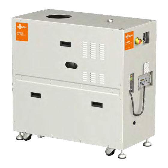
- Page 1 Instruction Manual COMBI Screw Vacuum Pumps and Boosters COBRA DS 3161 B 0870739180/-0002_en / Original instructions 18/11/2021...
- Page 2 WZ (MB) rotary lobes vacuum pump... . 13 Congratulations on your purchase of the Busch vacuum pump. With Oil level, pump not operating ....13 watchful observation of the field’s requirements, innovation and steady...
- Page 3 COBRA DS 3161 B DP Backing vacuum pump DP 600 C ESS Emergency stop switch Inlet MSH Main switch OUT Discharge (to silencer) MTB Pump terminal box Remote control COBRA DS 3161 B DS 3161 B Page 3 0870739180 (En)
- Page 4 TS 2 OSG 1 TS 1 DGR 1 FS 2 DGR 2 TS 4 FS 1 TS 3 TS 5 OSG 2 COBRA DP 600 C TS 2 Temperature switch, cooling liquid FS 2 Flow switch, cooling water CLP Glycol circulating pump temperature 100°C CWI Cooling wate outlet connection TS 3 Temperature sensor PT100...
- Page 5 OSG 3 OSG 4 FS 1 Flow switch, cooling liquid TS 6 TS 4 TS 3 OSG 1 TS 1 OSG 2 TS 2 FS 2 FS 1 DGR 1 DGR 1 DGR 2 Inlet Discharge DS 3161 B Page 5 0870739180 (En)
-
Page 6: Product Description
endplate of cylinder B-side. The flow of the cooling liquid is Product description controlled by a flow switch FS 1. If the flow is under 1 l/min during a minimum time of 30 seconds, then the pump stops. The temperature regulator TS 2 will give an emergency signal if the temperature of the cooling liquid is above 100°C. - Page 7 Filling in cooling liquid (CLF) Do not touch! – cooling liquid temperature See "Installation and Maintenance Instructions, Busch PLC and Busch Filling in oil (OFP) LCD (No. 0870758077)". On/ Off switch WARNING! The vacuum pump is delivered with a circuit breaker. The function...
- Page 8 Lock Out/ Tag Out procedure (Type 1 of COBRA DS vacuum pump electrical work) l Stop the pump with the remote control (press on STOP button during 10s) l Press on emergency stop button l Switch off the main disconnect switch DS 3161 B DL 3181 A DS 3161 B...
- Page 9 u Unscrew the fastening nuts underneath the pallet. Storage Temporary storage CAUTION l Make sure that the intake and exhaust flanges are closed (put on Do not work, walk or stand under suspended loads. the protective caps included in the delivery package of the vacuum pump) CAUTION l Store the vacuum pump...
-
Page 10: Installation And Start-Up
Make sure that the vacuum pump is placed on or fastened to a cuum pump. If you have any doubts, contact your Busch representa- horizontal surface tive. - Page 11 2 Nm is adhered to and check with a the vacuum pump. If you have any doubts, contact your Busch repre- calibrated torque wrench (Nuts M6).
- Page 12 Ethernet network connection (Busch Monitoring System) (option) Interface connection (50 poles) (option) PID Interface (9 poles) (option) The information concerning the use of the Busch PLC and the Busch LCD can be found in the Operation and Maintenance manual (Art-No. 0870758077). Phase L1...
- Page 13 COBRA NS (DP) vacuum pump CAUTION l Prepare the quantity of oil specified in the table “Oil quantity” NOTE: The quantity of oil specified in the installation handbook is of The vacuum pump must remain in a horizontal position when it has informative nature only.
- Page 14 WZ (MB) rotary lobes vacuum pump If the intake line is equipped with a shut-off device: l Make sure that the oil level still lies in the target circle of the oil u Open the shut-off device sight glasses If the intake line is not equipped with a shut-off device: If the oil level is below the target circle : l Remove the rubber plate from the intake flange and connect the u Fill in more oil into the two vacuum pumps...
- Page 15 – Drain the cooling water CAUTION u Pull off the connections for the inlet and outlet of the cooling water The surface temperature of the vacuum pump can exceed 50 °C when the vacuum pump is in operation. u Drain the cooling water completely u If necessary, drain the cooling water with the help of Danger of burns! compressed air to prevent any risk of frost or corrosion...
- Page 16 Description of the Load Lock operation mode: l LL Mode = Off u The mode « Load Lock » is de-activated, the module DP and the module MB, when present, operate constantly at their maximum frequency of rotation. NOTE: the parameters « DP (or MB) Current Level », « Time Before » and «...
- Page 17 Standard operational time chart Signal control mode (Select LL mode = EXTERN) LCD start or Remote start (tool pump) 1) Cold start delay (5 sec) 50/60Hz Pump speed Dry pump 90Hz 30Hz Booster 2) MB on delay Pump ready (pump tool) Process on (tool pump) pump start-up...
- Page 18 Current control mode (Select LL mode = AUTO) LCD start or Remote start (tool pump) 1) Cold start delay (5 sec) 50/60Hz Pump speed Dry pump 90Hz 30Hz Booster 2) MB on delay Pump ready (pump tool) open(on) close(off) open(on) close(off) close(off) open(on) Chamber open/close...
-
Page 19: Maintenance
[mm] around the machine must be set up. l Inspect the vacuum pump for leaks of cooling liquid - if there are leaks, repair the vacuum pump (Busch) CAUTION l Inspect the vacuum pump for leaks of cooling water - if there are leaks, repair the vacuum pump (Busch) The surface temperature of the vacuum pump can exceed 50°C... - Page 20 If the oil level lies below the target circle: l Drain the oil (see “Draining the oil”) u Top up with oil (see “Refilling oil”) l A main inspection of the vacuum pump (Busch) If the oil level exceeds the target circle: Lock Out/ Tag Out procedure u Check the condensate drain l Drain the oil (see “Draining the oil”)
- Page 21 If dark oil similar to the example shown is observed, you have to l Carefully remove the oil drain plugs again and drain any remaining contact the Busch Customer Service without delay. Oil change l Make sure that the seals of the drain plugs are not damaged and that they sit properly.
- Page 22 l Make sure that the oil level is in the target circle of the oil sight l Close the purge cap on cylinder endplate B-side glasses l Fill in again by filler hole until cooling liquid flows by purge cap of l Make sure that the seals of the filler cap are not damaged and that cylinder upper plate they sit properly.
-
Page 23: Removal From Service
Decontamination ), which can be downloaded from Checking the current consumption www.buschvacuum.com. Busch service will only accept vacuum pumps that come with a com- l Check the current intensity of the motors of the DP and MB pletely filled in and legally binding signed form. - Page 24 When the product has reached the end of its lifetime: – decontaminate the vacuum pump CAUTION Only authorised personnel may carry out dismantling work on the vacuum pump. Before work begins, the operator of the vacuum pump must fill in a form or a “Declaration of Decontamination” that provides information on possible dangers and appropriate measures.
-
Page 25: Oil Type/ Quantity
Make sure that the oil type corresponds to specification: – Busch YLC 250 B, Art. No. 0831 131 400 (0,5 l @ 1 kg) WARNING The use of chemically contaminated or polluted oil can lead to hazardous pump conditions which could cause personal injury. -
Page 26: Cooling Liquid Type/ Quantity
Cooling liquid type/ quantity Cooling liquid type l Make sure that the cooling liquid type corresponds to specifications : Specifications Zitrec M-25 (ready-to-use) 20 litres can 5 litres can part no. 0831 238 761 part no. 0831 563 469 Cooling liquid quantity The quantity of cooling liquid specified in this instructions manual is of informative nature only. - Page 27 Technical data DS 3161 B Technical data Nominal suction capacity 60 Hz /h (cfm) 3045 (1792) 7,5 x 10 Torr Ultimate pressure mbar 1,0 x 10 kW (MB: 90 Hz) Electric power capacity 11,8 60 Hz kW on idle mode at ultimate pressure (MB: 30 Hz) 60 Hz...
-
Page 29: Eu Declaration Of Conformity
This Declaration of Conformity and the CE-mark affixed to the nameplate are valid for the machine within the Busch scope of delivery. This Declaration of Conformity is issued under the sole responsibility of the manufacturer. When this machine is integrated into a superordinate machinery the manufacturer of the superordinate machinery (this can be the operating company, too) must conduct the conformity assessment process for the superordinate machine or plant, issue the Declaration of Conformity for it and affix the CE-mark. - Page 30 This Declaration of Conformity and the UKCA-mark affixed to the nameplate are valid for the machine within the Busch scope of delivery. This Declaration of Conformity is issued under the sole responsibility of the manufacturer. When this machine is integrated into a superordinate machinery the manufacturer of the superordinate machinery (this can be the operating company, too) must conduct the conformity assessment process for the superordinate machine or plant, issue the Declaration of Conformity for it and affix the UKCA-mark.
- Page 31 Note...
- Page 32 Busch Vacuum Solutions We shape vacuum for you. Argentina Denmark Malaysia South Africa info@busch.com.ar info@busch.dk busch@busch.com.my info@busch.co.za Australia Finland Mexico Spain sales@busch.com.au info@busch.fi info@busch.com.mx contacto@buschiberica.es Austria France Netherlands Sweden busch@busch.at busch@busch.fr info@busch.nl info@busch.se Bangladesh Germany New Zealand Switzerland sales@busch.com.bd info@busch.de sales@busch.co.nz...
Need help?
Do you have a question about the COMBI COBRA DS 3161 B and is the answer not in the manual?
Questions and answers