
Related Manuals for BUSCH COMBI COBRA DS 8161 F


Summary of Contents for BUSCH COMBI COBRA DS 8161 F
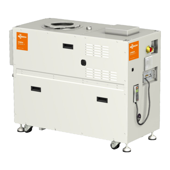
- Page 1 Instruction manual COMBI Screw Vacuum Pumps and Boosters COBRA DS 8161 F Ateliers Busch S.A. Zone industrielle, 2906 Chevenez, Switzerland 0870235853/-_en / Original instructions / Modifications reserved 07/12/2020...
-
Page 2: Table Of Contents
COBRA NS (DP) vacuum pump Oil level, pump not operating WY (MB) rotary lobes vacuum pump Congratulations on your purchase of the Busch vacuum pump. With Oil level, pump not operating watchful observation of the field’s requirements, innovation and steady... -
Page 3: Cobra Ds 8161 F
COBRA DS 8161 F IN Inlet connection OUT Discharge connection ECO Power connection PRV Nitrogen pressure reducer CWC Cooling water connection DGC Nitrogen connection OSG Oil sight glass CAO Extracting ventilator MB On/off switch , Main circuit breaker ESS Emergency stop switch(EMO) RF Ventilator PLC PLC box RC LCD... -
Page 4: Cobra Dp 600 C
COBRA DS 8161 F ECO Power connection DGC Nitrogen connection CWO Cooling water outlet connection CWI Cooling water inlet connection TS1 Temperature switch, oil temperature 120℃ FME Flow meter, nitrogen MV Solenoid valve, nitrogen system DGR1 Regulating valve, dilution gas DGR1 DGR2 DGR2 Regulating valve, dilution gas... - Page 5 CLP Recirculating pump CWI Cooling water inlet CWO Cooling water outlet CWV Cooling water regulating valve OSG4 DGR 2 Regulating valve, dilution gas DGR 1 Regulating valve, dilution gas FME Flow meter, nitrogen FS Flow switch, booster OSG3 FS1 Flow switch, cooling liquid FS 2 Flow switch, cooling water HE Heat exchanger OSG1...
-
Page 6: Product Description
Product description endplate of cylinder B-side. The flow of the cooling liquid is controlled by a flow switch FS 1. If the flow is under 1 l/min during a minimum time of 30 seconds, then the pump stops. The temperature regulator TS 2 will give an emergency signal if the temperature of the cooling liquid is above 100°C. -
Page 7: On/ Off Switch
W ARNING Filling in Hot surface cooling liquid (CLF) Do not touch See "Installation and Maintenance Instructions, Busch PLC and Busch LCD (No. 0870758077)". Filling in oil (OFP) On/ Off switch W ARNING The vacuum pump is delivered with a circuit breaker. The function... -
Page 8: Noise Emission
Lock Out/ Tag Out procedure (Type 1 of COBRA DS vacuum pump electrical work) Stop the pump with the remote control (press on STOP button during 10s) Press on emergency stop button Switch off the main disconnect switch ... -
Page 9: Lifting For Dp 0600 C
Unscrew the fastening nuts underneath the pallet. Storage Temporary storage CAUTION Make sure that the intake and exhaust flanges are closed (put on Do not work, walk or stand under suspended loads. the protective caps included in the delivery package of the vacuum pump) Store the vacuum pump CAUTION... -
Page 10: Installation And Start-Up
Make sure that the vacuum pump is placed on or fastened to a than the intake flange to prevent a drop in the performance of the va- horizontal surface cuum pump. If you have any doubts, contact your Busch representa- Make sure that the vacuum pump is level tive. -
Page 11: Nitrogen Connection
When connecting up the wires into the terminal box: please make sure the tightening torque of 2 Nm is adhered to and the vacuum pump. If you have any doubts, contact your Busch repre- check with a calibrated torque wrench (Nuts M6). -
Page 12: Equipment Connections (With Options)
(Busch Monitoring System) (option) Interface connection (50 poles) (option) PID Interface (9 poles) (option) The information concerning the use of the Busch PLC and the Busch LCD can be found in the Operation and Maintenance manual (Art-No. Phase L1 0870758077). -
Page 13: Cobra Ns (Dp) Vacuum Pump
COBRA NS (DP) vacuum pump CAUTION Prepare the quantity of oil specified in the table “Oil quantity” The vacuum pump must remain in a horizontal position when it has NOTE: The quantity of oil specified in the installation handbook is of been filled with oil. -
Page 14: Filling In Cooling Liquid
WY (MB) rotary lobes vacuum pump If the intake line is equipped with a shut-off device: Make sure that the oil level still lies in the target circle of the oil Open the shut-off device sight glasses If the intake line is not equipped with a shut-off device: If the oil level is below the target circle : Remove the rubber plate from the intake flange and connect the ... -
Page 15: Switching The Vacuum Pump On/ Off
– Drain the cooling water CAUTION Pull off the connections for the inlet and outlet of the cooling water The surface temperature of the vacuum pump can exceed 50 °C when the vacuum pump is in operation. Drain the cooling water completely ... -
Page 16: Maintenance
Inspect the vacuum pump for leaks of cooling liquid - if there are CAUTION leaks, repair the vacuum pump (Busch) Inspect the vacuum pump for leaks of cooling water - if there are Before maintenance work is started, a safety area of at least leaks, repair the vacuum pump (Busch) 610 [mm] around the machine must be set up. -
Page 17: Every 16 000 Hours Of Operation, At The Latest After 4 Years
Drain the oil (see “Draining the oil”) Top up with oil (see “Refilling oil”) If the oil level exceeds the target circle: A main inspection of the vacuum pump (Busch) Lock Out/ Tag Out procedure Check the condensate drain Drain the oil (see “Draining the oil”) -
Page 18: Checking The Colour Of The Oil
accidentally be switched on again If dark oil similar to the example shown is observed, you have to contact the Busch Customer Service without delay. Carefully remove the oil drain plugs again and drain any remaining Oil change Make sure that the seals of the drain plugs are not damaged and ... -
Page 19: Wy (Mb) Rotary Lobes Vacuum Pump
Make sure that the oil level is in the target circle of the oil sight Close the purge cap on cylinder endplate B-side glasses Fill in again by filler hole until cooling liquid flows by purge cap of ... -
Page 20: Checking The Cooling Water
Decontamination ), which can be downloaded from www.buschvacuum.com. Checking the current consumption Busch service will only accept vacuum pumps that come with a com- Check the current intensity of the motors of the DP and MB pletely filled in and legally binding signed form. -
Page 21: Removal From Service
When the product has reached the end of its lifetime: – decontaminate the vacuum pump CAUTION Only authorised personnel may carry out dismantling work on the vacuum pump. Before work begins, the operator of the vacuum pump must fill in a form or a “Declaration of Decontamination” that provides information on possible dangers and appropriate measures. -
Page 22: Oil Type/ Quantity
Make sure that the oil type corresponds to specification: – Busch YLC 250 B, Art. No. 0831 131 400 (0,5 l ≅ 1 kg) WARNING The use of chemically contaminated or polluted oil can lead to hazardous pump conditions which could cause personal injury. -
Page 23: Cooling Liquid Type/ Quantity
Cooling liquid type/ quantity Cooling liquid type Make sure that the cooling liquid type corresponds to specifications : Specifications Zitrec M-25 (ready-to-use) 25 litres can 5 litres can part no. 0831 563 468 part no. 0831 563 469 Cooling liquid quantity The quantity of cooling liquid specified in this instructions manual is of informative nature only. -
Page 24: Technical Data
Technical data Technical data DS 8161 F Nominal suction capacity 60 Hz /h (cfm) 6000 (3530) 7,5 x 10 Torr Ultimate pressure mbar 1,0 x 10 kW (MB: 90 Hz) Electric power 12,5 kW on idle capacity at ultimate 60 Hz mode (MB: 30 10,0 pressure... -
Page 25: Eu-Declaration Of Conformity
EU-Declaration of Conformity This Declaration of Conformity and the CE-mark affixed to the nameplate are valid for the machine within the Busch scope of delivery. This declara- t ion of Conformity is issued under the sole responsibility of the manufacturer. When this machine is integrated into a superordinate machinery the m anufacturer of the superordinate machinery (this can be the operating company, too) must conduct the conformity assessment process for the supe rordinate machine or plant, issue the Declaration of Conformity for it and affix the CE-mark. - Page 26 Note...
- Page 27 Note...
- Page 28 Israel Portugal United Arab Emirates info@busch.cl service_sales@busch.co.il busch@busch.pt sales@busch.ae China Italy Romania United Kingdom info@busch-china.com info@busch.it office@buschromania.ro sales@busch.co.uk Colombia Japan Russia info@buschvacuum.co info@busch.co.jp info@busch.ru info@buschusa.com Czech Republic Korea Singapore info@buschvacuum.cz busch@busch.co.kr sales@busch.com.sg www.buschvacuum.com 0870235853/-0002_en / © Ateliers Busch S.A .