
Subscribe to Our Youtube Channel
Related Manuals for BUSCH COBRA DS 2141 A


Summary of Contents for BUSCH COBRA DS 2141 A
- Page 1 COBRA Dry Screw Vacuum Pumps DS 2141 A Instruction Manual 0870741968 | -0003_en-US | Original instructions 9/20/2023...
-
Page 2: Table Of Contents
Table of Contents Table of Contents Preface ................................... Congratulations on your purchase ........................Product Description ............................. COBRA DS 2141 A ..............................Use ..................................Operating Principle ............................. 2.3.1 COMBI ..............................2.3.2 Gas Flow Checks ........................... Oil Circuit................................Cooling.................................. Nitrogen System..............................Optional Functions/ Use of Available Accessories .................. - Page 3 Table of Contents 6.2.2 Electrical Connection..........................6.2.3 Equipment Connections (with Options)..................... 6.2.4 Connection of Lines/ Pipes ........................6.2.5 Oil Filling ..............................6.2.6 Cooling Liquid Filling..........................6.2.7 Direct Cooling Checking ........................6.2.8 Nitrogen Supply Checking........................6.2.9 Operating Parameters Saving ......................Recommendations on Operation........................6.3.1 Application.............................
-
Page 4: Preface
1 | Preface Preface Congratulations on your purchase Congratulations on your purchase of the Busch vacuum pump. With watchful observation of the field’s requirements, innovation and steady development Busch delivers modern vacuum and pres- sure solutions worldwide. These operating instructions contain information for ●... -
Page 5: Product Description
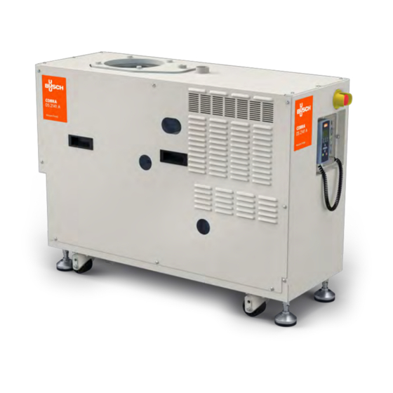
Product Description | 2 Product Description COBRA DS 2141 A OSG 3 OSG 1 OSG 2 Description Suction connection Discharge connection Cooling liquid glass Cooling water connections Nitrogen connections Emergency stop button Electrical connections Extracting ventilator Lifting eye bolt Handpad... - Page 6 2 | Product Description CWR 2 TS 2 TS 3 CWM 2 CWR 2 CWM 1 OSG 3 VSD 2 VSD 1 TS 1 DGR 1 OSG 3 Description Cooling liquid drain plug Cooling liquid sight glass Cooling water connections CWM 1 Cooling water flow meter CWM 2...
- Page 7 Product Description | 2 Process Gas Diagram Description Process gas inlet Process gas outlet Cooling water flow meter (CWM1) Cooling water switch (CWM 2) Cooling water regulating valve (CWR 1) Cooling water regulating valve (CWR 2) Variable speed drive DP/ MB (VSD) Heat exchanger (HE) Nitrogen flow meter, dilution gas (FME) Nitrogen pressure reducer (PRV)
-
Page 8: Use
2 | Product Description COBRA NS 0350 A PUMA WY 1251 B Description Inlet Outlet Booster lobe Cooling water Motor klixon The COBRA DS vacuum pumps are designed for use in the field of microelectronics and similar in- dustries. They can be used to suck gases and gas mixtures. WARNING When using toxic, inflammable and/or explosive gases, make sure that the system corre- sponds in design to applicable local and national safety regulations and that all applicable... -
Page 9: Operating Principle
2.3.1 COMBI The COBRA DS 2141 A vacuum pumps are a combination of a screw vacuum pump NS 0350 A (DP) and a Booster vacuum pump WY 1251 B (MB). The COMBI vacuum pumps are streamlined. The COBRA DS vacuum pumps are COBRA NS screw vacuum pumps with cooling water and nitrogen circuits. -
Page 10: Nitrogen System
● FME: nitrogen flow rate, dilution ● CWM: cooling water flow rate in motors/ transmission / variable speed drives See "Installation and Maintenance Instructions, Busch PLC and Busch LCD (No. 0870758077)". On/ Off Switch The vacuum pump is delivered with a circuit breaker. The function start/ stop can be done in Local by using the LCD controller or in Remote by the production machine. -
Page 11: Versions
Product Description | 2 Versions Further vacuum pump descriptions state the nominal displacement and the design level. Example: DS 2141 A DS = standard version 2141 = 1875 m A = Design Instruction Manual COBRA DS 2141 A_EN_en 11 | 60... -
Page 12: Safety
The maintenance instructions must be followed and observed. These installation and maintenance instructions must be read and understood before the vacuum pump is used. If you have any doubts, contact your Busch representative. Safety Information The vacuum pump is designed and manufactured in compliance with the latest technical standards and safety regulations. -
Page 13: Safety Stickers
Safety | 3 NOTE ... indicates helpful tips and recommendations, as well as information for efficient and trou- ble-free operation. CAUTION The COBRA DS system includes provision for the secondary containment of liquids leaks such as water and oil. Safety Stickers COBRA NS 0350 A Description Warning! Hot surface! Do not touch! -
Page 14: Noise Emission
3 | Safety COBRA DS 2141 A Noise Emission Refer to the table “Technical data” for the permissible noise levelling free field conditions according to EN ISO 2151. CAUTION The sound level of the vacuum pump within a certain perimeter of the vacuum pump is high. -
Page 15: Lock Out/ Tag Out Procedure (Type 1 Of Electrical Work)
Safety | 3 Type 3 Equipment is energized. Energized circuits are exposed and inadvertent contact with uninsulated energized parts is possible. Potential exposures are no greater than 30 volts rms, 42.4 volts peak, 60 volts dc or 240 volt-amp in dry locations. Type 4 Equipment is energized. -
Page 16: Seismic Zone Installation
3 | Safety Seismic Zone Installation Upon receipt, the vacuum pump is fixed on the transport pallet with two brackets. ● Convey the vacuum pump to its final location with a pallet truck before removing it from its sup- port. ●... -
Page 17: Information Over The Lubricants
NS 0350 A WY 1251 B Oil quantity (Liter) Oil type Busch YLC 250 B, Art. No. 0831 131 400 (0,5 l ≈ 1 kg) ● Replacement: After 5000 h (see “Maintenance Schedule [➔ 40]”). 3.8.2 Cooling Liquid Cooling liquid filling... -
Page 18: Transport
4 | Transport Transport The COBRA DS vacuum pumps are tested and checked in our factory before careful packing. Check the packaging for transport damage when the goods arrive. The vacuum pump can withstand tem- peratures between -25°C and +55°C during transport. Transport in Packed State Packed on a pallet, the vacuum pump can be moved with a hand forklift truck. - Page 19 Transport | 4 In case the vacuum pump was bolted to a pallet with fixing bolts: ● Unscrew the fixing bolts in the base frame. CAUTION In case of a vacuum pump filled with oil, make sure that by lifting the inclination angle of the vacuum pump do not exceed 5°...
-
Page 20: Storage
5 | Storage Storage Temporary Storage ● Make sure that the intake and exhaust flanges are closed (put on the protective caps included in the delivery package of the vacuum pump) ● Store the vacuum pump: ● if possible, the vacuum pump should be stored in its original packaging, ●... -
Page 21: Installation And Commissioning
Installation and Commissioning | 6 Installation and Commissioning Installation Prerequisites CAUTION In case of non-compliance with the installation prerequisites, particularly in case of insuffi- cient cooling: Risk of damage or destruction of the vacuum pump and its components! Risk of personal injury! The installation prerequisites must be complied with. - Page 22 6 | Installation and Commissioning NOTE 1° (german degree = 1° dGH) = 1,78° (french degree) = 1,25 e (english degree) = 17,9 mg/kg Ca- CO3 (american hardness). ● Make sure that the cooling water is neutral and clean. ● Make sure that the cooling water outlet is unpressurised. ●...
-
Page 23: Dimensional Drawing
Emergency stop Remote Control (moveable) Busch PLC ● Make sure that the vacuum pump is at least 1 meter away from any wall to ensure good cooling. ● Before any maintenance action, ensure a safety perimeter of at least 610 [mm] around the vacu- um pump. -
Page 24: Discharge Connection
– DN 160 ISO-K In the case of long intake lines, the line cross-section should be larger than the intake flange to pre- vent a drop in the performance of the vacuum pump. If you have any doubts, contact your Busch representative. -
Page 25: Cooling Water Connection
● Make sure that an overload cut-out according to EN 60204-1 is provided for the motor. ● Make sure that the drive of the vacuum pump is not disturbed by any electric or electromagnetic interferences. If you have any doubts, contact your Busch representative. Installation 6.2.1... -
Page 26: Electrical Connection
6 | Installation and Commissioning 6.2.2 Electrical Connection WARNING Risk of electrocution, risk of damage. Electrical installation must be performed by a suitably qualified electrician who knows and fol- lows the following regulations: ● IEC 364 or CENELEC HD 384 or DIN VDE 0100, ●... - Page 27 Installation and Commissioning | 6 Delta connection (low voltage): MB Motor Connection Motor connectors: Connection of motor temperature switch (recommended): Control voltage: ≤ 250 V Max current: 1.6 A MTS = Motor temperature switch (in motor coil) Delta connection (low voltage): Star connection (high voltage): Instruction Manual COBRA DS 2141 A_EN_en 27 | 60...
- Page 28 6 | Installation and Commissioning 6.2.2.1 Power Wiring Connection Power wiring 4 poles Phase L1 Phase L2 Phase L3 Ground 6.2.2.2 Power Connector on Rear Side Description Pump side Phase L1 (Pump side) Phase L2 (Pump side) Phase L3 (Pump side) Ground (Pump side) Mating connectors Phase 1 (Mating connectors)
-
Page 29: Equipment Connections (With Options)
Interface connection (50 poles) / PID In- Monitoring System - Option) terface The information concerning the use of the Busch PLC and the Busch LCD can be found in the Opera- tion and Maintenance manual (Art. No. 0870758077). 6.2.4 Connection of Lines/ Pipes ●... -
Page 30: Oil Filling
Oil filling NS 0350 A WY 1251 B Oil quantity (Liter) Oil type Busch YLC 250 B, Art. No. 0831 131 400 (0,5 l ≈ 1 kg) 6.2.5.1 COBRA NS 0350 A Oil Filling Description Oil fill plug B-side (OFP) - Page 31 Installation and Commissioning | 6 ● Make sure that the seal ring in the oil filler plugs is not damaged, replace plugs if necessary. Fit the oil filler plugs and tighten up. 6.2.5.2 PUMA WY 1251 B A Oil Filling Description Oil fill plug (OFP) Oil fill plug (OFP)
- Page 32 6 | Installation and Commissioning ● Unscrew the oil filler cap (OFP). ● Fill in oil. ● Make sure that the oil level lies between the MIN and MAX markings on the oil sight glasses. ● Make sure that the seals of the oil filler cap are not damaged. Replace them if necessary ●...
-
Page 33: Cooling Liquid Filling
Installation and Commissioning | 6 6.2.6 Cooling Liquid Filling NOTE The COBRA DS vacuum pumps are generally dispatched with cooling liquid already in the vac- uum pump. Before vacuum pump first startup, control the cooling liquid level. In the event of absence of one or the other of these lubricants, please carry out the filling (see “Cooling Liquid Type/ Quantity [➔ 56]”... -
Page 34: Direct Cooling Checking
6 | Installation and Commissioning ● Close the shut-off device. If the intake line is not equipped with a shut-off device: ● Place a rubber plate on the intake flange. ● Let the vacuum pump run for a few minutes. ●... - Page 35 Installation and Commissioning | 6 WARNING When using toxic, inflammable and/or explosive gases, make sure that the system corre- sponds in design to applicable local and national safety regulations and that all applicable safety measures are followed. All product-specific safety regulations must be observed. Solid particles must not get into the vacuum pump.
- Page 36 6 | Installation and Commissioning CAUTION The COBRA DS vacuum pumps are always delivered without oil, without cooling water and without cooling liquid. Operation without coolants will result in damage to the vacuum pump! CAUTION The cooling water flow, which is checked by the flow meter CWM1, must be at least 7 l/min. ●...
-
Page 37: Switching The Vacuum Pump On/ Off
Installation and Commissioning | 6 6.3.2 Switching the Vacuum Pump On/ Off 6.3.2.1 First Start-up of the System ● Make sure that the “Necessary installation instructions” are followed. If the system is equipped with a solenoid gate valve in the cooling water circuit: ●... -
Page 38: Maintenance
7 | Maintenance Maintenance DANGER Live wires. Risk of electrical shock. ● Electrical installation work must only be executed by qualified personnel. DANGER In case the vacuum pump has conveyed gases that have been contaminated with foreign ma- terials that are dangerous to health, the oil and condensates will also be contaminated. These foreign materials can infiltrate the pores, recesses, and other internal spaces of the vac- uum pump. - Page 39 Maintenance | 7 ● Stop the pump with the LCD control (press on STOP button during 10s). ● Press on emergency stop button. ● Switch off the main circuit breaker. ● Switch off the customer’s power supply. ● Switch off the water and nitrogen quick connections (inlet first, then outlet). ●...
-
Page 40: Maintenance Schedule
(contact Busch). ● Check the vacuum pump for cooling liquid leaks - in case of leaks have the vacuum pump repaired (contact Busch). ● Check the vacuum pump for cooling water leaks - in case of leaks have the vacuum pump repaired (contact Busch). -
Page 41: Lock Out/ Tag Out Procedure
Maintenance | 7 Interval Maintenance work Yearly ● If the intake is equipped with a sieve: If one or more of these accesso- ● Check the sieve at the intake and clean if necessary. ries are installed. ● Check the measuring and safety equipment for working or- der. -
Page 42: Oil Checking
NOTE Oil does not normally have to be refilled outside the recommended oil change intervals. A drop in the oil level indicates a fault (see "Alarms and warnings -> Busch PLC and Busch LCD"). CAUTION Only fill in oil through the oil filler opening. -
Page 43: Oil Color Inspection
If the oil becomes dark or looks different from the initial color: ● Change the oil immediately, see Oil Change. You can consult your Busch representative in order to find out why this color change has occurred. 7.2.4 Oil Change... - Page 44 7 | Maintenance 7.2.4.1 Used Oil Draining NOTE After switching off the vacuum pump at normal operating temperature wait no more than 20 minutes before the oil is drained. ● Make sure that the vacuum pump is switched off and cannot accidentally be switched on again. ●...
- Page 45 Maintenance | 7 7.2.4.2 New Oil Filling COBRA NS (DP) vacuum pump: ● Prepare the quantity of oil needed (see “Oil Type/ Quantity [➔ 55]”). CAUTION The use of chemically contaminated or polluted oil can lead to hazardous pump conditions which could cause personal injury. NOTE The quantity of oil specified in the Instruction Manual is of informative nature only.
-
Page 46: Cooling Liquid Checking
7 | Maintenance NOTE The quantity of oil specified in the Instruction Manual is of informative nature only. Check the oil level with the help of the various oil sight glasses on the vacuum pump. ● Make sure that the drain plugs have been fitted properly and that they do not leak. CAUTION Only fill in oil through the oil filler opening. -
Page 47: Cooling Liquid Refilling
Maintenance | 7 7.3.2 Cooling Liquid Refilling NOTE Cooling liquid does not normally have to be refilled outside the recommended change inter- vals. A drop in the level of the liquid indicates a fault (see “Troubleshooting [➔ 53]”). ● Make sure that the vacuum pump has been switched off and that it cannot be switched on again accidentally. -
Page 48: Additional Checking
7 | Maintenance ● Stop fill in. ● Close the drain plug. ● Make sure that the seal of the filler cap is not damaged and that they sit properly. Replace them if necessary. ● Screw on the filler cap again. ●... -
Page 49: Overhaul
● Decontaminate the machiine as much as possible and state the contamination status in a ‘Dec- laration of Contamination’. Busch will only accept machiine accompanied by a signed, fully completed and legally binding "dec- laration of contamination", downloadable from the following link: buschvacuum.com/declaration-of- contamination. -
Page 50: Removal From Service
9 | Removal from Service Removal from Service DANGER Live wires. Risk of electrical shock. ● Electrical installation work must only be executed by qualified personnel. CAUTION Hot surface. Risk of burns! ● Before doing anything that requires touching the machine, let it cool down first. Temporary Removal from Service Before disconnecting the intake and exhaust lines and switching off the cooling water and nitrogen lines, make sure that the lines have adjusted to atmospheric pressure. -
Page 51: Dismantling And Disposal
Removal from Service | 9 Dismantling and Disposal DANGER In case the vacuum pump has conveyed gases that have been contaminated with harmful for- eign material which are harmful to health, the oil and the condensates will also be contami- nated with harmful foreign material. -
Page 52: Spare Parts
Risk of premature failure! Loss of efficiency! ● The exclusive use of Busch genuine spare parts and consumables is recommended for the correct functioning of the machine and to validate the warranty. There are no standard spare parts kits available for this product. -
Page 53: Troubleshooting
Busch). Solid foreign matter has en- ● Remove the solid foreign tered the machine. matter or repair the ma- chine (contact Busch). ● Install an inlet filter if neces- sary. A temperature sensor has ● Let the machine cool down. - Page 54 Oil Change. The machine runs too hot. ● See problem "The machine runs too hot". For resolution of problems not listed in the troubleshooting table, please contact your Busch repre- sentative. 54 | 60 Instruction Manual COBRA DS 2141 A_EN_en...
-
Page 55: Oil Type/ Quantity
Oil Type/ Quantity | 12 Oil Type/ Quantity 12.1 Oil Type Make sure that the oil type corresponds to specifications: YLC 250 B Part number 0.5 L packaging (~1 kg) 0831 131 400 Part number 1.0 L packaging (~2 kg) 0831 108 878 Part number 5.0 L packaging (~10 kg) 0831 108 879 CAUTION... -
Page 56: Cooling Liquid Type/ Quantity
13 | Cooling Liquid Type/ Quantity Cooling Liquid Type/ Quantity 13.1 Cooling Liquid Type Make sure that the Cooling Liquid type corresponds to specifications: Zitrec M-25 (ready-to-use) Part number 25 L packaging 0831 563 468 Part number 5 L packaging 0831 563 469 The cooling liquid Zitrec M-25 is ready-to-use and does not require additional water. -
Page 57: Technical Data
Technical Data | 14 Technical Data DS 2141 A Nominal pumping speed m³/h 1875 Ultimate pressure TORR 0.00225 hPa (mbar) 0.003 Nominal motor rating kW (72 Hz) backing pump Nominal motor rating kW (90 Hz) vacuum booster Power consumption at ultimate pressure (MB: 90 Hz;... -
Page 58: Eu Declaration Of Conformity
EU Declaration of Conformity This Declaration of Conformity and the CE-markings affixed to the nameplate are valid for the machiine within the Busch scope of delivery. This Decla- ration of Conformity is issued under the sole responsibility of the manufacturer. -
Page 59: Uk Declaration Of Conformity
UK Declaration of Conformity This Declaration of Conformity and the UKCA-markings affixed to the nameplate are valid for the machiine within the Busch scope of delivery. This Dec- laration of Conformity is issued under the sole responsibility of the manufacturer. - Page 60 With a network of over 60 companies in more than 40 countries and agencies worldwide, Busch has a global presence. In every country, highly competent local personnel delivers custom-tailored support backed by a global network of expertise. Wherever you are.
Need help?
Do you have a question about the COBRA DS 2141 A and is the answer not in the manual?
Questions and answers